Automated inhalation toxicology exposure system and method

a toxicology and inhalation system technology, applied in the field of multianimal inhalation exposure systems, can solve the problems of not being able to automatically control the inhalation, not being able to provide for the conditioning of the inhalation environment, and related-art multianimal inhalation system not being able to provide for the different exposure durations

Inactive Publication Date: 2008-05-27
ARMY GOVERNMENT OF THE UNITED STATES THE AS REPRESENTED BY THE SEC OF THE THE
View PDF47 Cites 47 Cited by
  • Summary
  • Abstract
  • Description
  • Claims
  • Application Information

AI Technical Summary

Problems solved by technology

The inventors have discovered that related-art multi-animal inhalent systems do not tend to provide for the conditioning of an inhalent environment prior to exposing the animals to the inhalent environment.
The inventors have discovered that related-art multi-animal inhalent systems do not tend to provide for differing exposure durations during which animals are exposed to the same inhalent environment.
The inventors have discovered that related-art multi-animal inhalent systems do not automatically control inhalent dose delivery and recording functions on an identified-animal basis.

Method used


Image

  • Automated inhalation toxicology exposure system and method
  • Automated inhalation toxicology exposure system and method
  • Automated inhalation toxicology exposure system and method

Examples


Embodiment Construction

A. Devices

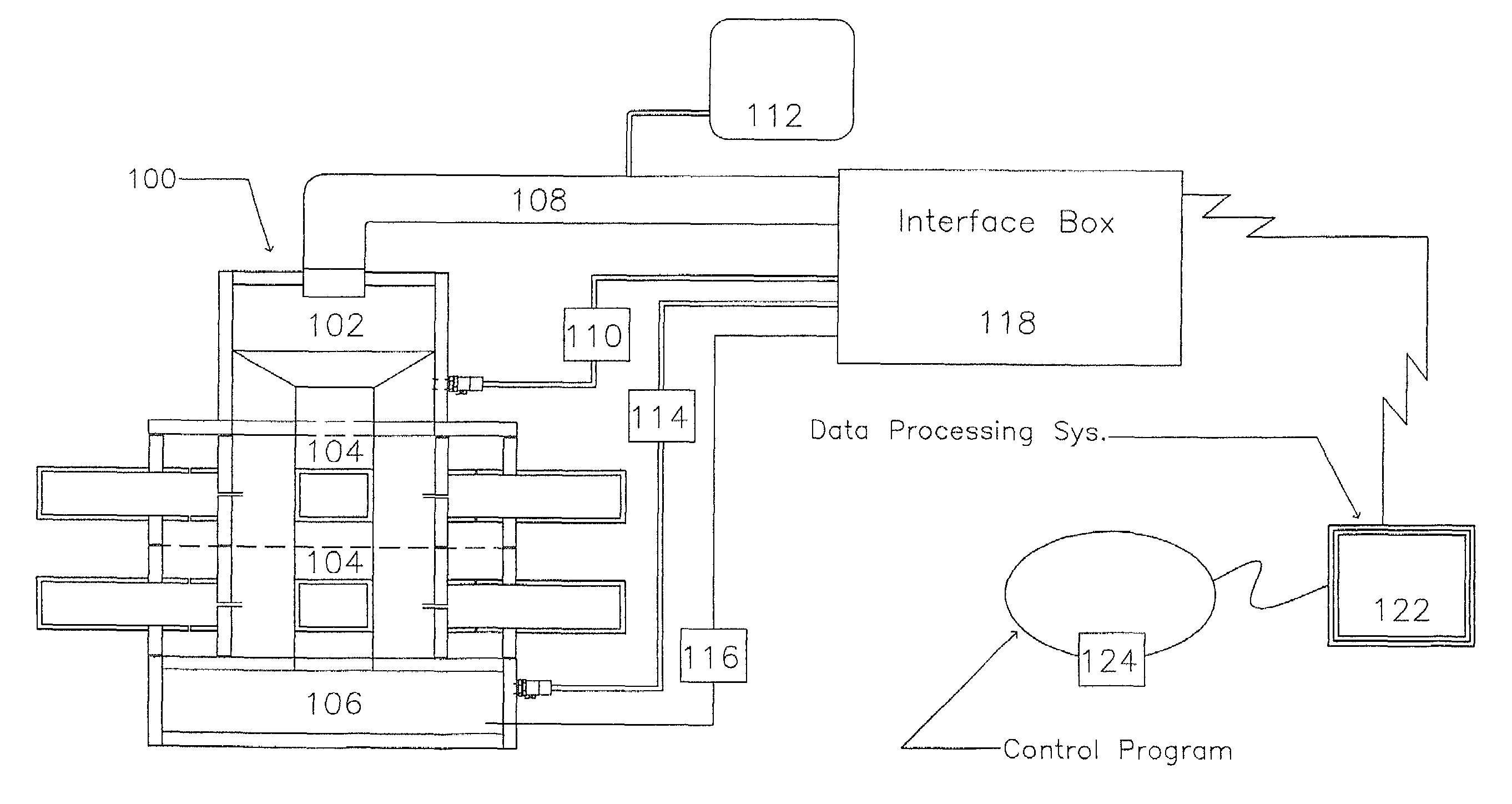
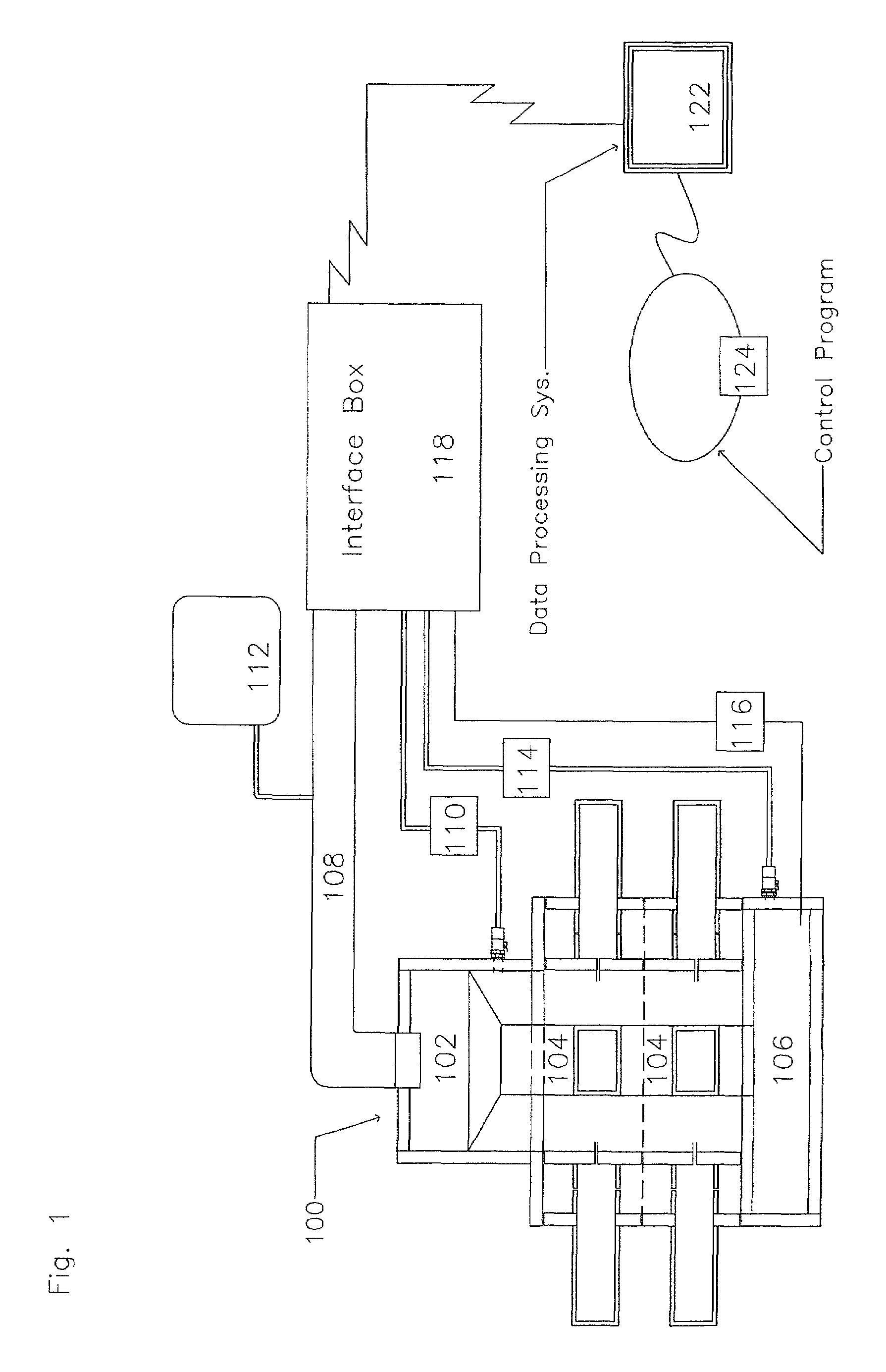
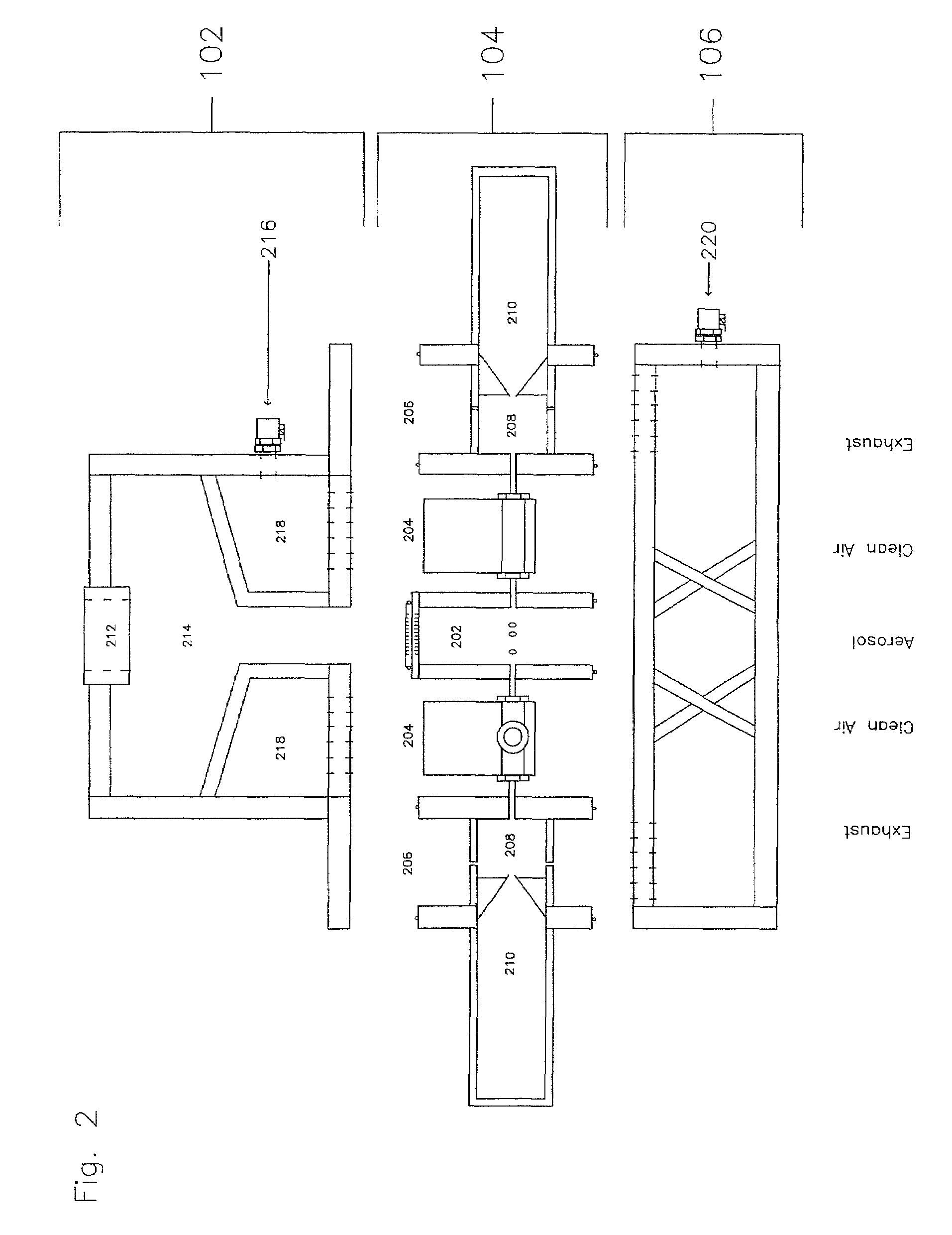
[0026]A high level pictographic representation of an exposure system and associated hardware is included as FIG. 1. Depicted is exposure tower 100 composed of three distinct sections: input module 102, exposure modules 104, and exhaust module 106. Shown connected to the input module are inhalent air input hose 108 and clean air input hose 110. Integral with inhalent air input hose 108 is inhalent dissemination device 112. Inhalent dissemination device 112 is meant to be indicative of a variety of different devices for dispersing organic or inorganic substances in an aerosol, gas, fume, dry powder, or other suitable form. Connected to exhaust module 106 is output air hose 114. Shown coupled to exposure tower 100 is also wire bundle 116, meant to be indicative of a plurality of wires connecting a variety of electronic devices housed in exposure tower 100 to interface box 118. Operably coupled to interface box 118 are also inhalent input air hose 108, clean air input hose 110...


PUM


Abstract

In one embodiment, a method includes but is not limited to: conditioning an inhalent environment; exposing a first organism to the inhalent environment for a first-organism duration of time; and exposing a second organism to the inhalent environment for a second-organism duration of time. In one embodiment, a method includes but is not limited to: conditioning an inhalent environment; exposing a first organism to the inhalent environment until a calculated first-organism delivered dosage meets or exceeds a predefined first-organism target dosage; and exposing a second organism to the inhalent environment until a calculated second-organism delivered dosage meets or exceeds a predefined second-organism target dosage. In one embodiment, a method includes but is not limited to: detecting a first organism via a first-organism biochip device implanted in the first organism; and controlling a first-organism dosage in response to the first-organism biochip device. In addition to the foregoing, other method embodiments are described in the claims, drawings, and text forming a part of the present application. In one or more various embodiments, related systems include but are not limited to circuitry and / or programming for effecting the foregoing-referenced method embodiments; the circuitry and / or programming can be virtually any combination of hardware, software, and / or firmware configured to effect the foregoing-referenced method embodiments depending upon the design choices of the system designer. In one embodiment, a system includes but is not limited to: an inhalent manifold; a first independently-controllable exposure unit coupled to said inhalent manifold; a second independently-controllable exposure unit coupled to said inhalent manifold; and an exposure control system operably coupled to either or both said first independently-controllable exposure unit and said second independently-controllable exposure unit.

Description

CROSS-REFERENCE TO RELATED APPLICATION[0001]The present patent application is a continuation-in-part of and hereby incorporated by reference in its entirety, U.S. patent application Ser. No. 09 / 919,741, entitled Automated Inhalation Toxicology Exposure System, filed Jul. 31, 2001, now U.S. Pat. No. 6,904,912 B2, and naming Chad J. Roy and Justin M. Hartings as inventors, which claims the benefit of U.S. Provisional Patent Application No. 60 / 267,233, filed Jan. 31, 2001, entitled Automated Inhalation Toxicology Exposure System, and naming Chad J. Roy and Justin M. Hartings as inventors; the present patent application also hereby incorporates by reference in its entirety any subject matter which was itself incorporated by reference into the previously-referenced U.S. patent application Ser. No. 09 / 919,741, entitled Automated Inhalation Toxicology Exposure System, such as U.S. Provisional Patent Application No. 60 / 267,233.STATEMENT REGARDING FEDERALLY SPONSORED RESEARCH OR DEVELOPMENT[...

Claims


Application Information

Patent Timeline
Patent Type & Authority Patents(United States)
IPC IPC(8): A61M11/00A01K1/03A61M15/00A61M16/00A61B5/08A61D7/04
CPCA01K1/031A61D7/04A61B5/0806A61B5/08A61B2503/40A61B2503/42A61B5/4845
Inventor ROY, CHAD J.HARTINGS, JUSTIN M.
Owner ARMY GOVERNMENT OF THE UNITED STATES THE AS REPRESENTED BY THE SEC OF THE THE
Why Eureka
Try Eureka