Modification of lung region flow dynamics using flow control devices implanted in bronchial wall channels

a flow control device and lung region technology, applied in the direction of tubular organ implants, blood vessels, bronchi, etc., can solve the problems of reducing the ability of one or both lungs to fully expel air, less tone of diseased tissue, and inability to maintain the narrow airway open,

Inactive Publication Date: 2005-03-31
PULMONX
View PDF99 Cites 90 Cited by
  • Summary
  • Abstract
  • Description
  • Claims
  • Application Information

AI Technical Summary

Benefits of technology

[0016] Disclosed is a flow control device for placement in a bronchial wall of a bronchial passageway in a patient's lung, the bronchial wall having inner and outer surfaces. The flow control device comprises a tubular body having first and second ends and a passage therethrough, the tubular body being configured to extend through the bronchial wall with the passage in communication with the bronchi

Problems solved by technology

Certain pulmonary diseases, such as emphysema, reduce the ability of one or both lungs to fully expel air during the exhalation phase of the breathing cycle.
The problem is further compounded by the diseased, less elastic tissue that surrounds the very narrow airways that lead to the alveoli, which are the air sacs where oxygen-carbon dioxide exchange occurs.
The diseased tissue has less tone than healthy tissue and is typically unable to maintain the narrow airways open until the end of the exhalation cycle.
This traps air in the lungs and exacerbates the already-inefficient breathing cycle.
The trapped air causes the tissue to become hyper-expanded and no longer able to effect efficient oxygen-carbon dioxide exchange.
By taking up more of the pleural space, the hyper-expanded lung tissue reduces the amount of space available to accommodate the healthy, functioning lung tissue.
As a result, the hyper-expanded lung tissue causes inefficient breathing due to its own reduced functionality and because it adversely affects the functionality of adjacent healthy tissue.
However, such a conventional surgical approach is relatively traumatic and invasive, and, like most surgical procedures, is not a viable op

Method used


Image

  • Modification of lung region flow dynamics using flow control devices implanted in bronchial wall channels
  • Modification of lung region flow dynamics using flow control devices implanted in bronchial wall channels
  • Modification of lung region flow dynamics using flow control devices implanted in bronchial wall channels

Examples


Embodiment Construction

[0083] Unless defined otherwise, all technical and scientific terms used herein have the same meaning as is commonly understood by one of skill in the art to which the invention(s) belong. Disclosed are various devices and method for treating bronchopulmonary diseases.

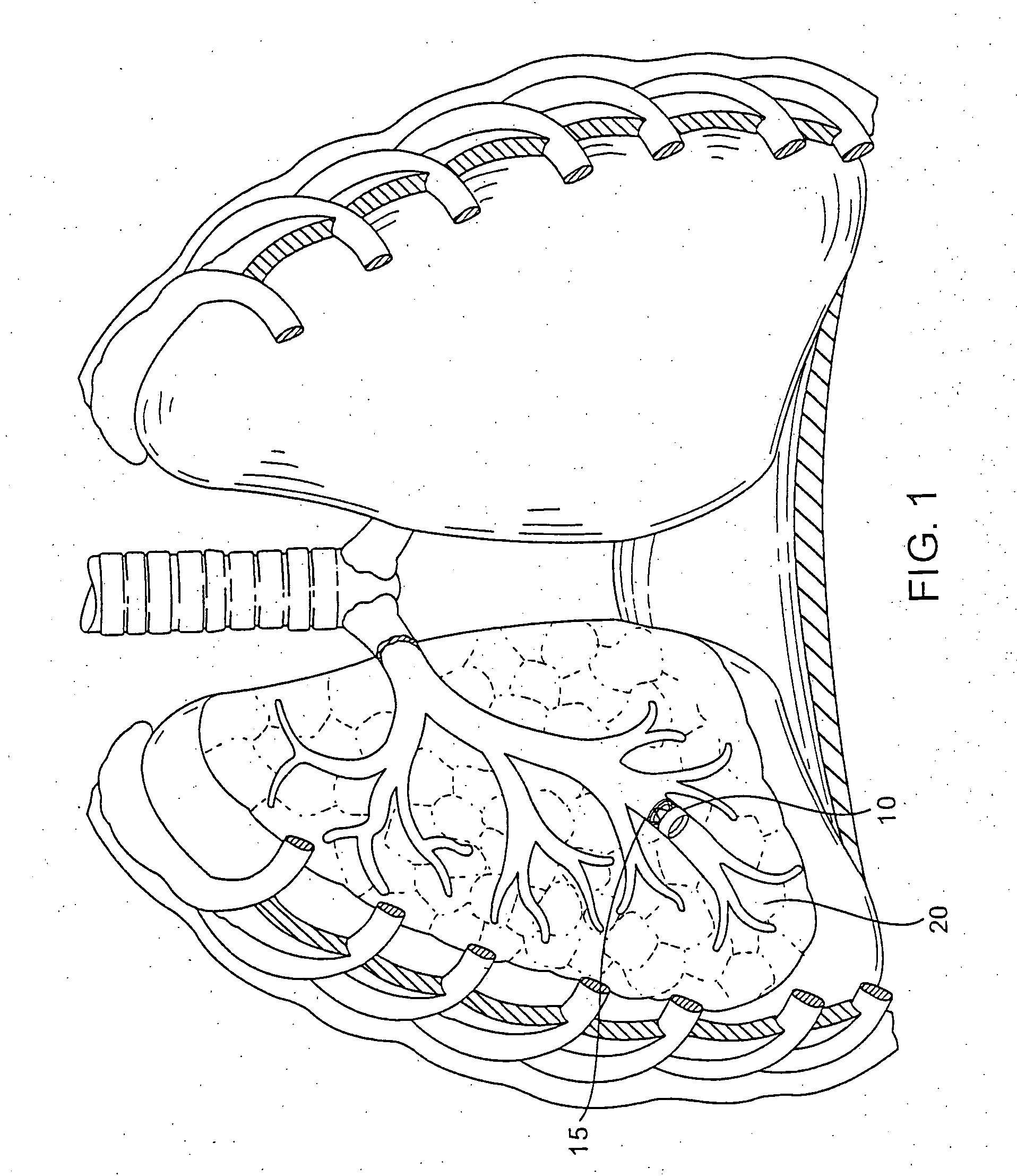
[0084] Exemplary Lung Regions

[0085] Throughout this disclosure, reference is made to the term “lung region”. As used herein, the term “lung region” refers to a defined division or portion of a lung. For purposes of example, lung regions are described herein with reference to human lungs, wherein some exemplary lung regions include lung lobes and lung segments. Thus, the term “lung region” as used herein can refer, for example, to a lung lobe or a lung segment. Such nomenclature conform to nomenclature for portions of the lungs that are known to those skilled in the art. However, it should be appreciated that the term “lung region” does not necessarily refer to a lung lobe or a lung segment, but can refer to some othe...


PUM


Abstract

A desired fluid flow dynamic to a lung region can be achieved by deploying various combinations of flow control devices and bronchial isolation devices in one or more bronchial passageways that communicate with the lung region. The flow control devices are implanted in channels that are formed in the walls of bronchial passageways of the lung. The flow control devices regulate fluid flow through the channels. The bronchial isolation devices are implanted in lumens of bronchial passageways that communicate with the lung region in order to regulate fluid flow to and from the lung region through the bronchial passageways.

Description

REFERENCE TO PRIORITY DOCUMENT [0001] This application claims priority of co-pending U.S. Provisional Patent Application Ser. No. 60 / 384,247 entitled “Implantable Bronchial Isolation Devices and Lung Treatment Methods”, filed May 28, 2002. Priority of the aforementioned filing date is hereby claimed, and the disclosure of the Provisional Patent Application is hereby incorporated by reference in its entirety. [0002] This application is a continuation-in-part of U.S. patent application Ser. No. 10 / 270,792, filed Oct. 10, 2002 and entitled “Bronchial Flow Control Devices and Methods of Use”, which is hereby incorporated by reference in its entirety.BACKGROUND OF THE INVENTION [0003] 1. Field of the Invention [0004] This invention relates generally to methods and devices for use in performing pulmonary procedures and, more particularly, to procedures for treating lung diseases. [0005] 2. Description of the Related Art [0006] Certain pulmonary diseases, such as emphysema, reduce the abil...

Claims


Application Information

Patent Timeline
IPC IPC(8): A61F2/04A61F2/06A61F2/24
CPCA61F2/04A61F2/06A61F2/2412A61F2002/043A61F2/2427A61F2/91A61F2/2418
Inventor FIELDS, ANTONYHENDRICKSEN, MICHAELHUNDERTMARK, RONALD
Owner PULMONX
Why Eureka
Try Eureka