Spine distraction implant

a technology of implant and spinal canal, applied in the field of spinal canal implant, can solve the problems of reducing the foraminal area, radicular pain, neck pain and muscle weakness, etc., and achieve the effect of reducing the restriction of vessels and nerves, and increasing the volume of spinal canal

Inactive Publication Date: 2008-04-10
KYPHON
View PDF0 Cites 114 Cited by
  • Summary
  • Abstract
  • Description
  • Claims
  • Application Information

AI Technical Summary

Benefits of technology

[0029] Other implants and methods within the spirit and scope of the invention can be used to increase the vol

Problems solved by technology

Spinal stenosis results in a reduction foraminal area (i.e., the available space for the passage of nerves and blood vessels) which compresses the cervical nerve roots and causes radicular pain.
Another symptom of spinal stenosis is myelopathy, which results in neck pai

Method used


Image

  • Spine distraction implant
  • Spine distraction implant
  • Spine distraction implant

Examples


first embodiment

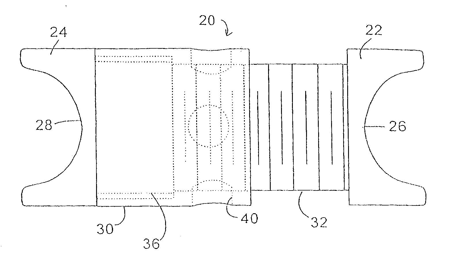
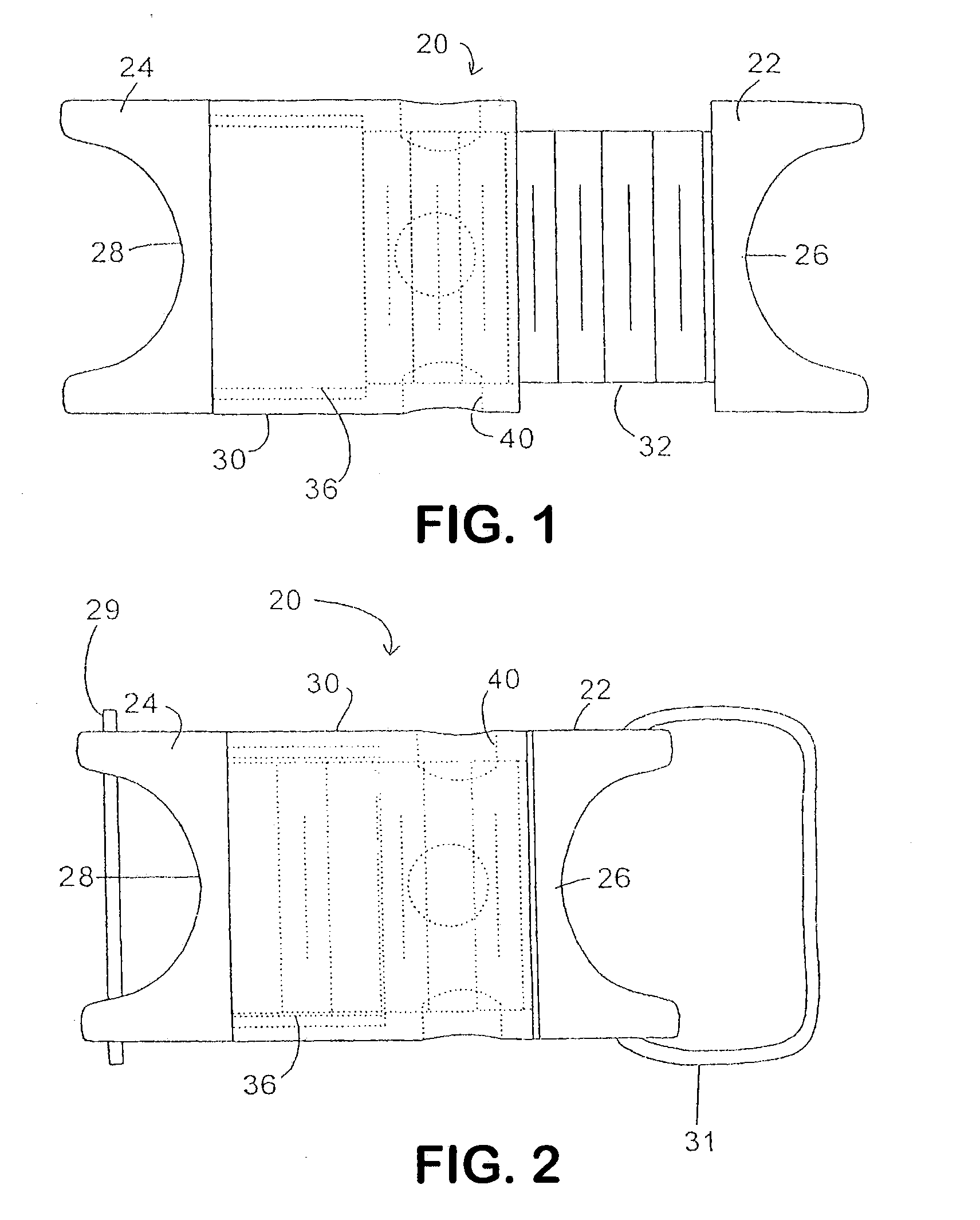
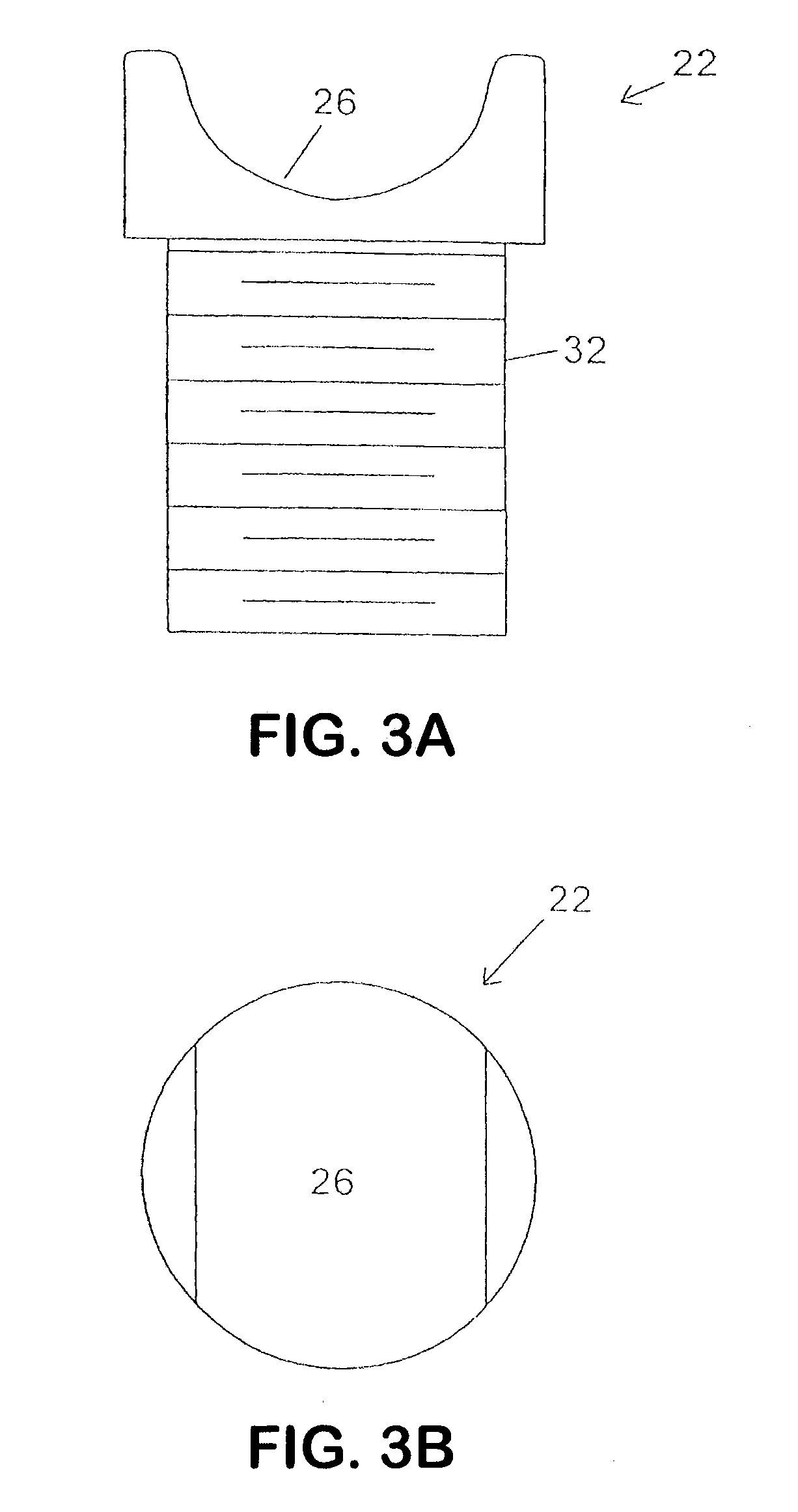
[0146] the invention is shown in FIGS. 1-5a, 5b. Implant 20 includes first and second forked ends 22 and 24, each defining a saddle 26, 28 respectively. The forked ends 22, 24 are mated using an interbody piece 30. As can be seen in FIGS. 3a, 3b, the first forked end 22 includes a threaded shaft 32 which projects rearwardly from the saddle 26. The threaded shaft 32 fits into the threaded bore 34 (FIG. 4a) of the interbody piece 30.

[0147] The second forked end 24 (FIGS. 5a, 5b) includes a smooth cylindrical shaft 36 which can fit into the smooth bore 38 of the interbody piece 30.

[0148]FIG. 1 shows the implant 20 in a fully extended position, while FIG. 2 shows the implant in an unextended position. In the unextended position, it can be seen that the threaded shaft 32 of the first forked end 22 fits inside the hollow cylindrical shaft 36 of the second forked end 24.

[0149] For purposes of implantation between adjacent first and second spinous processes of the spinal column, the impla...

embodiment 110

[0162] The embodiment of implant 130 is not circular in overall outside appearance, as is the embodiment 110 of FIGS. 14 and 15. In particular, with respect to the embodiment of implant 130 of FIGS. 16 and 17, this embodiment is truncated so that the lateral side 140, 142 are flattened with the upper and lower sides 144, 146 being elongated in order to capture and create a saddle for the upper and lower spinous processes. The upper and lower sides, 144, 146 are rounded to provide a more anatomical implant which is compatible with the spinous processes.

[0163] If it is desired, and in order to assure that the first member 132 and the second member 134 are aligned, key 148 and keyway 150 are designed to mate in a particular manner. Key 148 includes at least one flattened surface, such as flattened surface 152, which mates to an appropriately flattened surface 154 of the keyway 150. In this manner, the first member is appropriately mated to the second member in order to form appropriate...


PUM

PropertyMeasurementUnit
Lengthaaaaaaaaaa
Lengthaaaaaaaaaa
Lengthaaaaaaaaaa

Abstract

A spine distraction implant alleviates pain associated with spinal stenosis and facet arthropathy by expanding the volume in the spine canal and/or neural foramen. The implant provides a spinal extension stop while allowing freedom of spinal flexion. An interspinous process implant with a selectably expandable spacer can be placed between adjacent spinous processes. a device implanted between the spinous processes of adjacent vertebrae of the spine can be used for relieving pain associated with the vertebrae and surrounding tissues and structures by maintaining and/or adding distraction between adjacent vertebrae. A tissue expander can be adapted to move from a first insertion position, for ease of implantation between spinous processes, to a second retention position that prevents displacement of the implant. An embodiment of a system can include an implant having a spacer with a thickness and a wing, wherein a first configuration of the wing has a first height substantially similar to the thickness and wherein the wing is adapted to be selectably arranged in a second configuration such that the wing has a second height greater than the first height. A periphery of the implant has a shape generally conformal with a shape of an inner surface of a cannula and a cross-sectional diameter smaller than an inner diameter of the cannula. The cannula is inserted such that a proximal end of the cannula is arranged between the adjacent spinous processes. The implant is then urged into position between the adjacent spinous processes by way of the cannula, and subsequently arranged in a second configuration to fix the implant in position.

Description

CROSS-REFERENCES TO RELATED APPLICATIONS [0001] The present application is a continuation-in-part of U.S. patent application Ser. No. 11 / 092,862, filed on Mar. 29, 2005; is a divisional of U.S. patent application Ser. No. 09 / 842,819, filed on Apr. 26, 2001, now issued as U.S. Pat. No. 7,201,751; which is a continuation-in-part of U.S. patent application Ser. No. 09 / 579,039, filed on May 26, 2000, now U.S. Pat. No. 6,451,019; which is a continuation-in-part of U.S. patent application Ser. No. 09 / 473,173, filed on Dec. 28, 1999, now U.S. Pat. No. 6,235,030; which is a continuation of U.S. Ser. No. 09 / 179,570, filed on Oct. 27, 1998, now U.S. Pat. No. 6,048,342; which is a continuation-in-part of U.S. patent application Ser. No. 08 / 958,281, filed on Oct. 27, 1997, now U.S. Pat. No. 5,860,977; which is a continuation-in-part of U.S. patent application Ser. No. 08 / 778,093, filed on Jan. 2, 1997 now U.S. Pat. No. 5,836,948. [0002] The present application is also a continuation-in-part of ...

Claims


Application Information

Patent Timeline
IPC IPC(8): A61F2/44A61B17/58
CPCA61B17/66A61B17/7065A61K31/37A61B17/7071A61B2017/00557A61B17/7068
Inventor ZUCHERMAN, JAMES F.HSU, KEN Y.WINSLOW, CHARLES J.KLYCE, HENRY A.YERBY, SCOTT A.FLYNN, JOHN J.MITCHELL, STEVEN T.MARKWART, JOHN A.
Owner KYPHON
Why Eureka
Try Eureka