
Methods and devices for combined gastric restriction and electrical stimulation

a gastric restriction and combined technology, applied in the field of methods and devices for implanting devices, can solve the problems of impracticality, dangerous or detrimental to the health of patients, and the length of the connector is short, and the effect of reducing the interior volume of the organ

Inactive Publication Date: 2006-04-06
GERTNER MICHAEL
View PDF91 Cites 109 Cited by
  • Summary
  • Abstract
  • Description
  • Claims
  • Application Information

AI Technical Summary

Benefits of technology

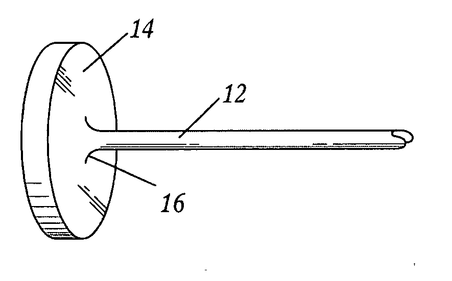
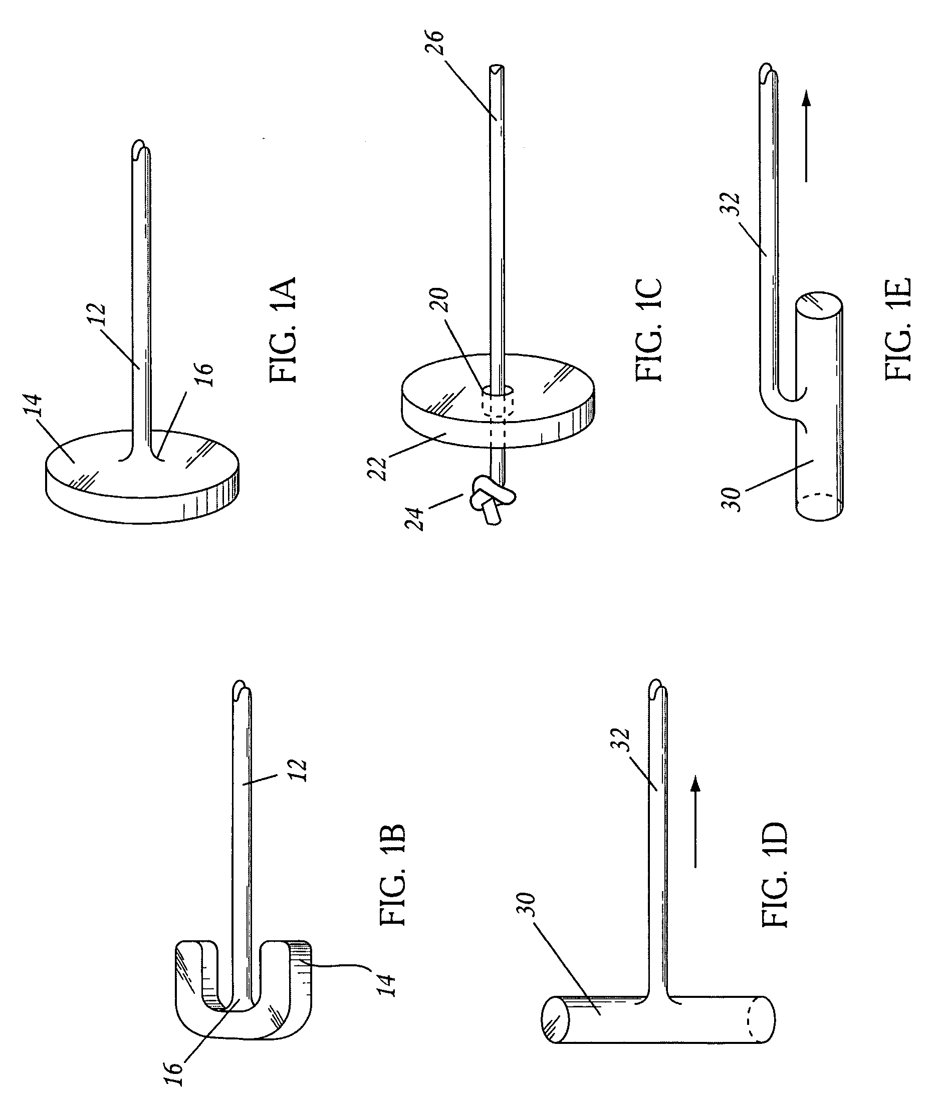
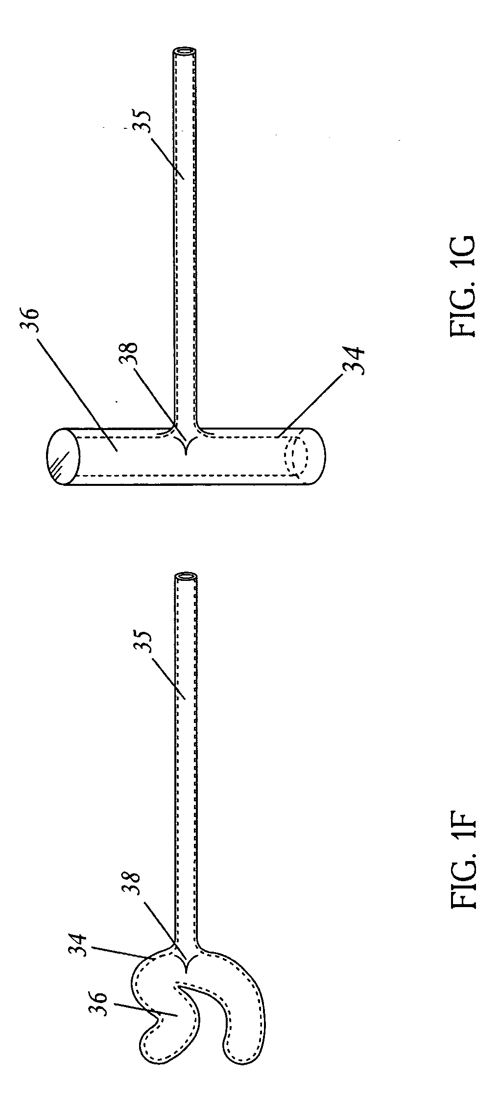
[0017] One embodiment of the present invention is a method for reducing the interior volume of an organ comprising passing a first end of a first surgical instrument through the patient's skin, through a first exterior surface of the organ, through the interior of the organ, and then through a second exterior surface of the organ, so that the surgical instrument traverses the organ, deploying a first anchor from the surgical instrument wherein the first anchor is located adjacent to the second exterior surface of the organ, partially or completely withdrawing the surgical instrument, deploying a second anchor wherein the second anchor is located adjacent to the first exterior surface of the organ, providing a connector between the first and second anchors, wherein the length of the connector between the first and second anchors is such that the first and second anchors urge the first and second exterior surfaces of the organ toward each other, thereby reducing the volume of the organ. In some embodiments, the first and second anchors are deployed from the same surgical instrument. Another aspect of the invention is a method of reversing the volume reducing procedure by cutting or otherwise dividing the one or more connectors between the first and second anchors. In another embodiment of the method, the organ is a gastrointestinal organ. The method may further comprise creating a space outside the organ adjacent to the second exterior surface thereof by introducing a volume-filling substance into a potential space adjoining the second exterior surface. The potential space can be expanded by the injection of a gas, liquid, gel, foam, or solid, into the potential space, by the inflation of a balloon placed in the potential space, or by blunt dissection. The method may further comprise insufflating the organ prior to the passing of the first end of a surgical instrument through a first exterior surface of the organ. In some embodiments, the patient's skin is overlying the patient's stomach, the organ is the patient's stomach, the first exterior surface is the anterior wall of the stomach, the second exterior surface is the posterior wall of the stomach, and the potential space is the lesser sac of the peritoneum. The method may further comprise urging the anterior and posterior walls of the stomach closer together by shortening the length of the connector between the first and the second anchors. In some embodiments, the surgical instrument is inserted into the patient's abdomen by directly penetrating the patient's skin and abdominal wall, by passing the surgical instrument through a laparoscopic port, or by passing the surgical instrument through an incision in the patient's skin and abdominal wall.
[0019] Another embodiment of the invention is a fastening assembly, comprising a first anchor, a second anchor, and a connector, wherein the first anchor comprises a relatively planar body attached to the connector, the body of the first anchor having a relatively planar deployed profile and a reduced profile configuration, wherein the second anchor comprises a relatively planar body, a hole or other passageway approximately in the center of the body of sufficient diameter to allow passage of the connector through the hole or other passageway, one, two or more gripping elements projecting into the hole or other passageway, and one, two or more attachment structures accessible from a top surface of the body, the body of the second anchor having a relatively planar deployed profile and a reduced profile configuration, and wherein the gripping elements prevent movement of the second anchor along the longitudinal axis of the connector in the direction away from the first anchor when the connector is disposed in the hole or other passageway when the second anchor is in its deployed configuration.
[0029] In any of the embodiments, the body of the second anchor can be inflatable, wherein the second anchor has a relatively planar deployed profile when inflated and a reduced profile configuration when uninflated, and wherein the second anchor is readily deformable when uninflated.

Problems solved by technology

Many of the procedures performed in the past have proven to be impractical, dangerous, or detrimental to the health of the patients and are now of historical importance only.
While patients initially lost a great deal of weight, liver failure or liver damage occurred in over one-third of the patients which necessitated reversal of the surgical procedure.
Despite the efficacy of the Roux procedure and the recent laparoscopic improvements, it remains a highly invasive procedure with substantial morbidity including a 1-2% surgical mortality, a 20-30% incidence of pulmonary morbidity such as pneumonia, pulmonary embolism, etc., and a 1-4% chance of leak at the anastamotic site which can result in a spectrum of consequences including an extended hospital stay to death.
There is also a substantial rate of anastamotic stricture which results in severe lifestyle changes for patients.
The largest problem from the perspective of the patient is that the Roux-en-Y is not reversible, which dramatically limits the number of patients willing to undergo the procedure.
In particular, it severely limits the number of procedures which can or should be performed on adolescents.
Although less invasive than the Roux procedure and potentially reversible, the LAP-BAND™ is nonetheless quite invasive.
Endoscopic procedures to manipulate the stomach are time consuming because of the technical difficulty of the endoscopy; they also require a large endoscope through which many instruments need to be placed for these complex procedures.
Due to the large girth of the endoscope, patients typically will require general anesthesia, limiting the “non-invasive” aspects of the procedure.
Such skill adaptation can take a significant amount of time, which will limit adoption of the procedure by the physician community.
A further issue is that there is a limitation on the size of the anchors which can be placed because the endoscope has a maximum size.

Method used


Image

  • Methods and devices for combined gastric restriction and electrical stimulation
  • Methods and devices for combined gastric restriction and electrical stimulation
  • Methods and devices for combined gastric restriction and electrical stimulation

Examples


Embodiment Construction

Anatomy of the Stomach

[0065] The region behind the stomach is referred to as the lesser peritoneal sac. It is a potential space between the retroperitoneum and the posterior wall of the stomach. To the left of the midline, the posterior wall of the stomach is generally free from the peritoneal surface of the retroperitoneum. To the right of the midline, the posterior wall of the stomach is more adherent to the retroperitoneum although the adherence is generally loose and the adhesions can be broken up rather easily with gentle dissection.

[0066] The stomach is comprised of several layers. The inner layer is the mucosa. The next layer is the submucosa followed by the outer muscular layers. Surrounding the muscular layers is the serosal layer. This layer is important with regard to implants and healing because it is the adhesive layer of the stomach; that is, it is the layer which, when breached, heals with scar tissue formation. Implants adhering to this layer are less likely to mi...


PUM


Abstract

Disclosed are methods and apparatus for implantation into the walls of an organ such as the stomach. Deformable or inflatable anchors with a connector between are used to pull the walls of the organ together, or to implant devices in the wall of the organ. Also disclosed are surgical instruments useful in practicing the disclosed methods.

Description

RELATED APPLICATIONS [0001] The present application is a continutation of U.S. Non-Provisional patent application Ser. No. 10 / 974,248 filed Oct. 27, 2004 by Michael Gertner, M.D. entitled “Devices and Methods to Treat a Patient,” which claims priority to U.S. Provisional Patent Application Ser. No. 60 / 556,004 filed Mar. 23, 2004 by Michael Gertner, M.D., entitled “BARIATRIC DEVICES AND IMPLANTATION METHODS,” to U.S. Provisional Patent Application Ser. No. 60 / 584,219 filed Jul. 1, 2004 by Michael Gertner, M.D., entitled “DEVICES AND METHODS FOR PERCUTANEOUS GASTROPLASTY,” and to U.S. Provisional Patent Application Ser. No. 60 / 603,944 filed Aug. 23, 2004 by Michael Gertner, M.D., entitled “DEVICES AND METHODS TO TREAT MORBID OBESITY,” all of which are herein incorporated by reference in their entirety.BACKGROUND OF THE INVENTION [0002] 1. Field of the Invention [0003] The present invention relates to methods and apparatus for implanting devices in the wall of a hollow organ, including...

Claims


Application Information

Patent Timeline
Patent Type & Authority Applications(United States)
IPC IPC(8): A61N1/05A61B17/00A61B17/04A61B17/06A61B17/08A61B17/28A61F5/00
CPCA61B17/00234A61B17/0401A61B17/0469A61B17/0487A61B17/29A61B2017/00398A61B2017/00827A61B2017/00871A61B2017/0404A61B2017/0409A61B2017/0417A61B2017/0445A61B2017/0454A61B2017/0456A61B2017/0458A61B2017/0464A61B2017/0488A61B2017/0496A61B2017/06052A61F5/0076A61F5/0086
Inventor GERTNER, MICHAEL
Owner GERTNER MICHAEL
Learn More