Eureka AIR delivers breakthrough ideas for toughest innovation challenges, trusted by R&D personnel around the world.

Method of preparing a machining process and chamfering station

Active Publication Date: 2019-08-15
GLEASON PFAUTER MASCHFAB
View PDF14 Cites 0 Cited by
  • Summary
  • Abstract
  • Description
  • Claims
  • Application Information

AI Technical Summary

Benefits of technology

The present invention relates to a method for accurately positioning a tool or workpiece in a gear measurement. The method involves using a non-contact centering sensor and a dedicated axis of motion to bring the tool or workpiece into a tooth gap of the workpiece. The method can be performed using a star-shaped tool, and the positioning movement can be done using a second axis of motion that is parallel to the rotation axis of the workpiece. The method allows for faster and more accurate positioning of the tool or workpiece, and can be used in a variety of gear measurement applications.

Problems solved by technology

Although non-contact centering sensors are mostly used today, there may be a risk of inaccuracy in determination of the rotary position of the workpiece (that is, the position of the center of a tooth slot of the workpiece) due to an inaccuracy in the position and / or the positioning of such a sensor with respect to a fixed machine side reference as for instance a slide unit carrying the tool.

Method used


Image

  • Method of preparing a machining process and chamfering station
  • Method of preparing a machining process and chamfering station
  • Method of preparing a machining process and chamfering station

Examples


Embodiment Construction

[0033]The details of the invention will now be discussed with reference to the accompanying drawings which illustrate the invention by way of example only. Furthermore, this specification does not seek to describe or limit the subject matter covered by any claims in any particular part, paragraph, statement or drawing of the application. The subject matter should be understood by reference to the entire specification, all drawings and any claim below. The invention is capable of other constructions and of being practiced or being carried out in various ways. Also, it is understood that the phraseology and terminology used herein is for the purposes of description and should not be regarded as limiting.

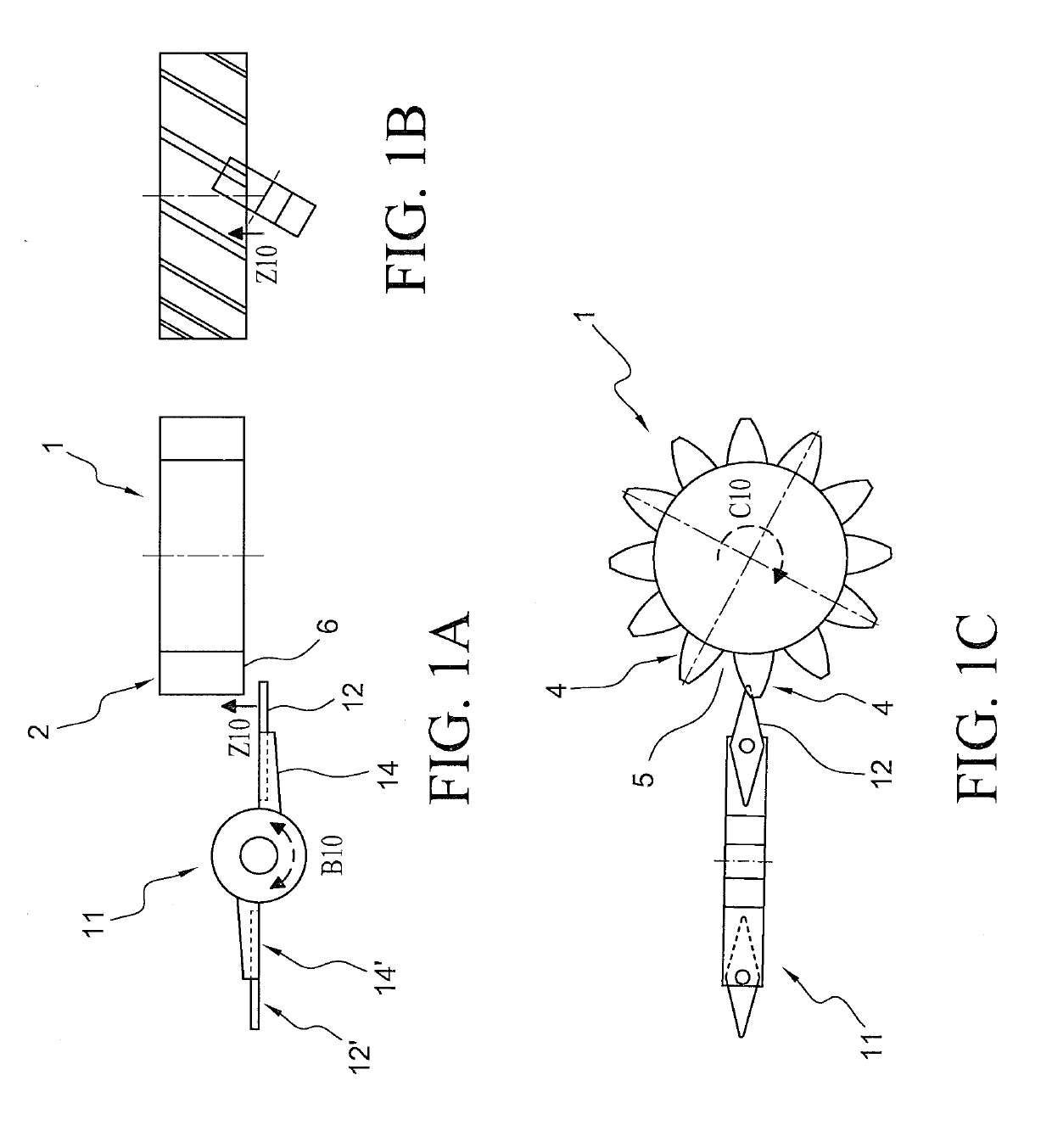
[0034]In the following, with reference to FIG. 1, in particular FIG. 1C, a method is described in which a star-like working tool 11 is brought with one of its two teeth between two teeth 4 of a toothing 2 of workpiece 1, departing from an unknown rotary position of said teeth 4 and too...


PUM

PropertyMeasurementUnit
Thicknessaaaaaaaaaa
Lengthaaaaaaaaaa

Abstract

A method of preparing a machining process of a toothed workpiece rotatably drivable around its rotation axis, the machining process to be executed by a tool rotatably drivable around its rotation axis, wherein, for establishing a synchronized matching engagement of the tool with the workpiece toothing, a contact with the workpiece can be or is generated by performing a movement via a positioning axis, and, by means of a surveillance of a movement dedicated to an axis of motion, a contact to the workpiece is used for establishing information about a relative rotary position of the workpiece, whereby the contact is made by a portion of the tool and the dedicated axis of motion is an axis capable to move or rotate the workpiece or the tool but which is not the positioning axis.

Description

FIELD OF THE INVENTION[0001]The invention relates to a method of preparing a machining process for a toothed workpiece, such as a gear, rotatably drivable around its rotation axis, the machining g process to be executed by a tool rotatably drivable around its rotation axis, wherein, for establishing a synchronized matching engagement of the tool with the workpiece toothing, a contact with the workpiece can be or is generated by performing a movement via a positioning axis, and, by means of a surveillance of a movement dedicated to an axis of motion, a contact to the workpiece is used for establishing information about a relative rotary position of the workpiece.BACKGROUND OF THE INVENTION[0002]Such a machining process of an already toothed workpiece can be for instance a chamfering operation of the tooth edges of the workpiece with a rotating cutting tool, as for instance disclosed in DE 10 2011 110 911 A1.[0003]Before the chamfering operation may start, one has, however, to ensure ...

Claims


Application Information

Patent Timeline
IPC IPC(8): B23F19/12
CPCB23F19/102B23F23/12B23F23/1218B23F19/10G05B19/186G01B5/166G01B5/163G01B5/202
Inventor LEICHT, BERNHARDMUNDT, ERIC G.
Owner GLEASON PFAUTER MASCHFAB
Why Eureka
Eureka Blog
Learn More