Part Marking System And Method Of Marking Parts

Inactive Publication Date: 2019-08-15
TRITON AUTOMATION GRP LLC
View PDF13 Cites 4 Cited by
  • Summary
  • Abstract
  • Description
  • Claims
  • Application Information

AI Technical Summary

Benefits of technology

The patent describes a part marking system that includes a marking conveyor, a position verification member, and a robotic arm with a laser marking member. The system is designed to position and laser etch indicia onto parts as they move on the marking conveyor. The system can also include a part positioning assembly and a part discharging assembly for efficient part processing. The technical effects of the system include improved accuracy in part positioning and laser etching, as well as improved part processing speed and efficiency.

Problems solved by technology

Second, after the laser etching process, which takes a few seconds, the part is removed.
The process is therefore quite labor intensive and also quite time consuming.
Furthermore, the use of fixtures requires additional storage thereof, when not in use, as well as added costs.

Method used


Image

  • Part Marking System And Method Of Marking Parts
  • Part Marking System And Method Of Marking Parts
  • Part Marking System And Method Of Marking Parts

Examples


Embodiment Construction

[0036]While this disclosure is susceptible of embodiment in many different forms, there is shown in the drawings and described herein in detail a specific embodiment(s) with the understanding that the present disclosure is to be considered as an exemplification and is not intended to be limited to the embodiment(s) illustrated.

[0037]It will be understood that like or analogous elements and / or components, referred to herein, may be identified throughout the drawings by like reference characters. In addition, it will be understood that the drawings are merely schematic representations of the invention, and some of the components may have been distorted from actual scale for purposes of pictorial clarity.

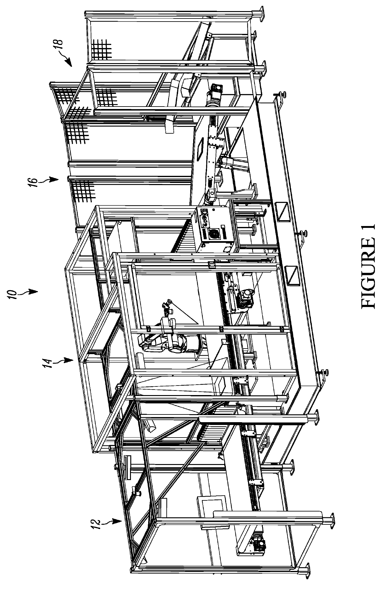
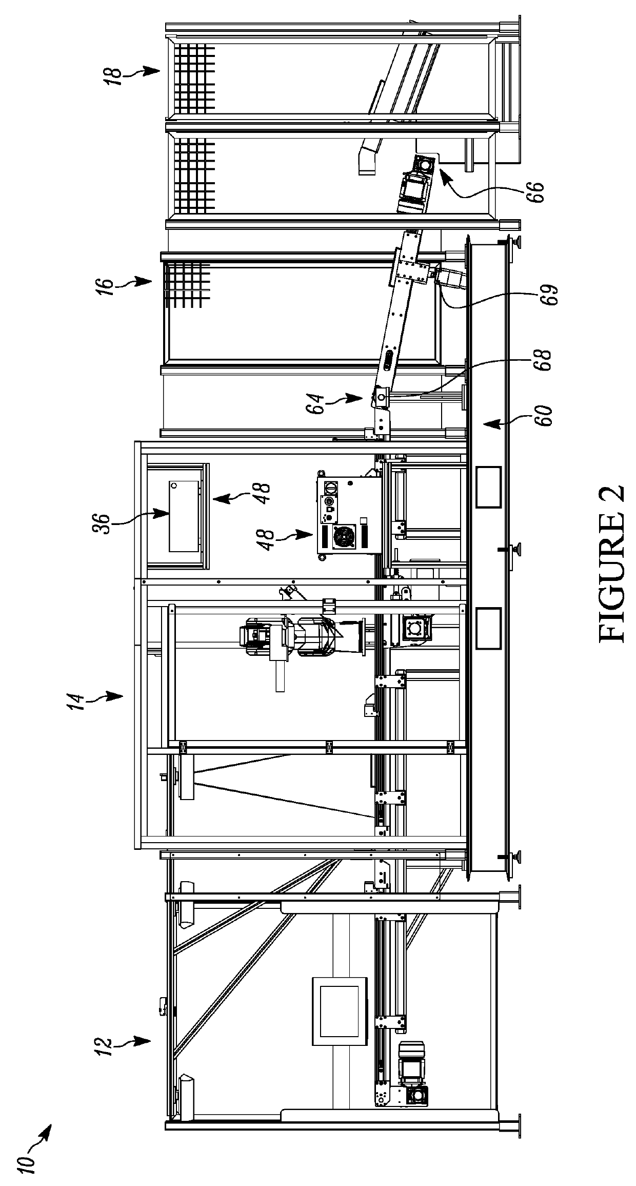
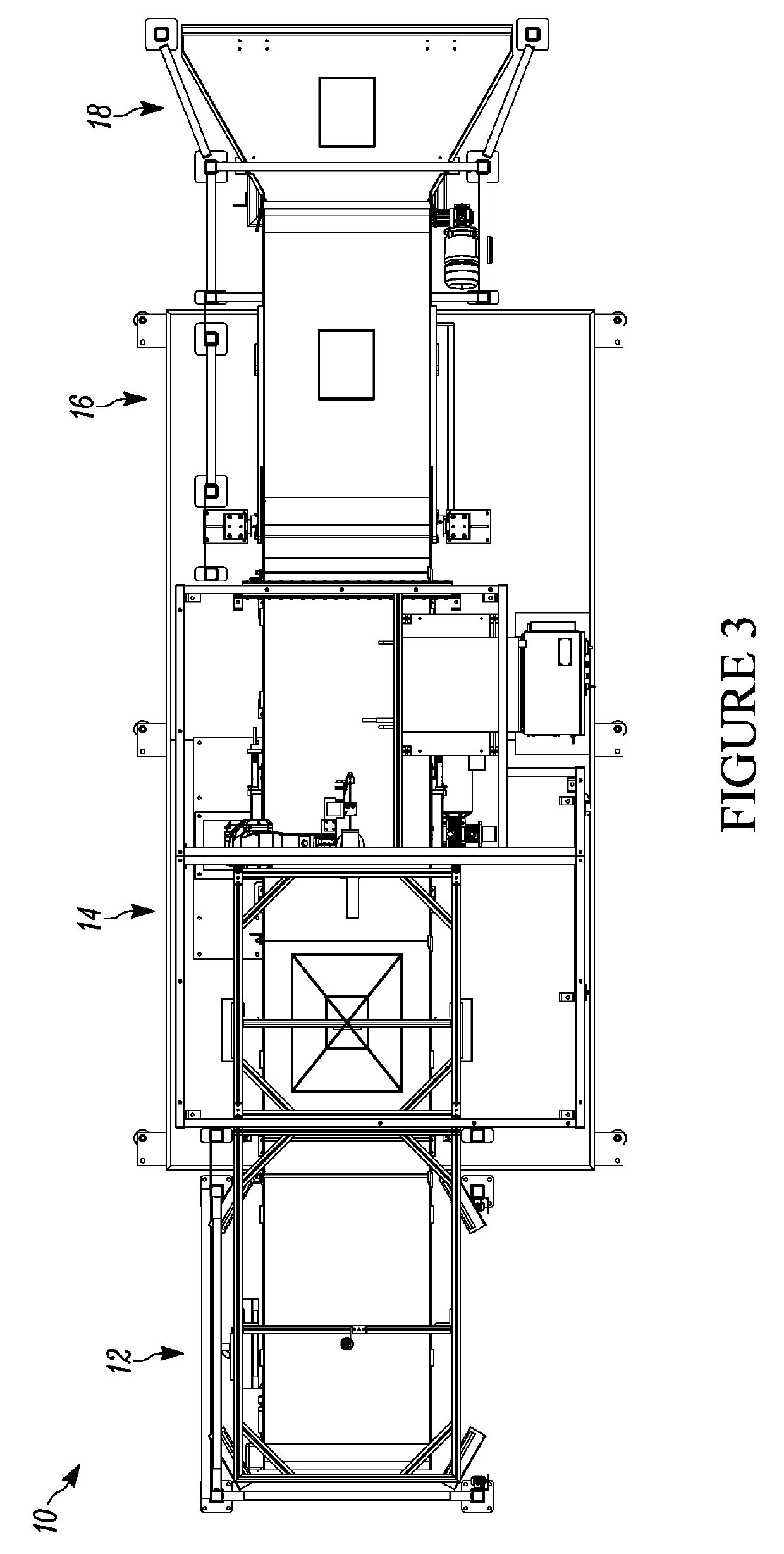
[0038]Referring now to the drawings and in particular to FIG. 1, the part marking system and method of marking parts is disclosed. The part marking system is shown generally at 10. The system is generally configured for use in a number of different environments for purposes of marking ...


PUM

PropertyMeasurementUnit
Angleaaaaaaaaaa
Speedaaaaaaaaaa
Proximity effectaaaaaaaaaa

Abstract

A part marking system comprising a part marking assembly having a marking conveyor, a position verification member and a marking structure. The marking conveyor includes a first end and a second end. The position verification member is associated with the marking conveyor and is structurally configured to determine the position of a part on the marking conveyor. The marking structure includes a robotic arm positioned in proximity to the marking conveyor, that has a laser marking member at a working end thereof. The laser marking member is structurally configured to laser etch indicia onto a part on the marking conveyor. The robotic arm is structurally configured to move the laser marking member to the proper orientation based on the position of the part, to, in turn, laser etch indicia onto a part while the part is on the marking conveyor and moving on the marking conveyor between the first end and the second end.

Description

CROSS-REFERENCE TO RELATED APPLICATION[0001]N / ABACKGROUND OF THE DISCLOSURE1. Field of the Disclosure[0002]The disclosure relates in general to automation equipment, and more particularly, to a part marking system and a method of marking parts. It will be understood that for purposes of the disclosure, the terms part and component are used interchangeably, and it will be understood that when reference is made to either, what is meant is any part, component, subassembly, assembly, or structure that is to receive a laser etching, which may comprise a part number, assembly number, bar code, date / time stamp, a manufacturing location, symbol, drawing or other indicia.2. Background Art[0003]With increased automation and computer control of processes and assemblies, it has been increasingly desirable to imprint data onto, for example, a part. Whereas in the past, a part may only include a part number or the like, it has become desirable to provide additional information on the part, includ...

Claims


Application Information

Patent Timeline
IPC IPC(8): B23K26/362B23K26/08B23K31/12B41M5/24
CPCB23K26/362B23K26/0838B23K26/0884B23K31/12B41M5/24B41M5/26
Inventor AUSTIN, SCOTTPELOSO, PHILIP
Owner TRITON AUTOMATION GRP LLC
Why Eureka
Try Eureka