
Pipe fittings having integrated thermoplastic with improved melt-flow characteristics for cured in place pipe systems and associated method of use

a technology of thermoplastic and pipe fittings, which is applied in the direction of pipe joints, flanged joints, coatings, etc., can solve the problems of high failure rate, difficult installation of replacement fittings, and critical deterioration of segments of pipes, so as to improve the resistance to leakage and deterioration

Active Publication Date: 2019-08-15
INFRASTRUCTURE TECH LLC
View PDF13 Cites 2 Cited by
  • Summary
  • Abstract
  • Description
  • Claims
  • Application Information

AI Technical Summary

Benefits of technology

This patent describes a way to strengthen and protect pipes from leaks and deterioration. The process involves adding a reinforcement layer to the inside of the pipe and then attaching fittings to the ends of the pipe. These fittings are then connected to adjoining pipe segments using bolts. Gaskets are placed between the fittings to create a tight and flexible structure that is resistant to leaks and damage. This process makes the pipe stronger and more durable.

Problems solved by technology

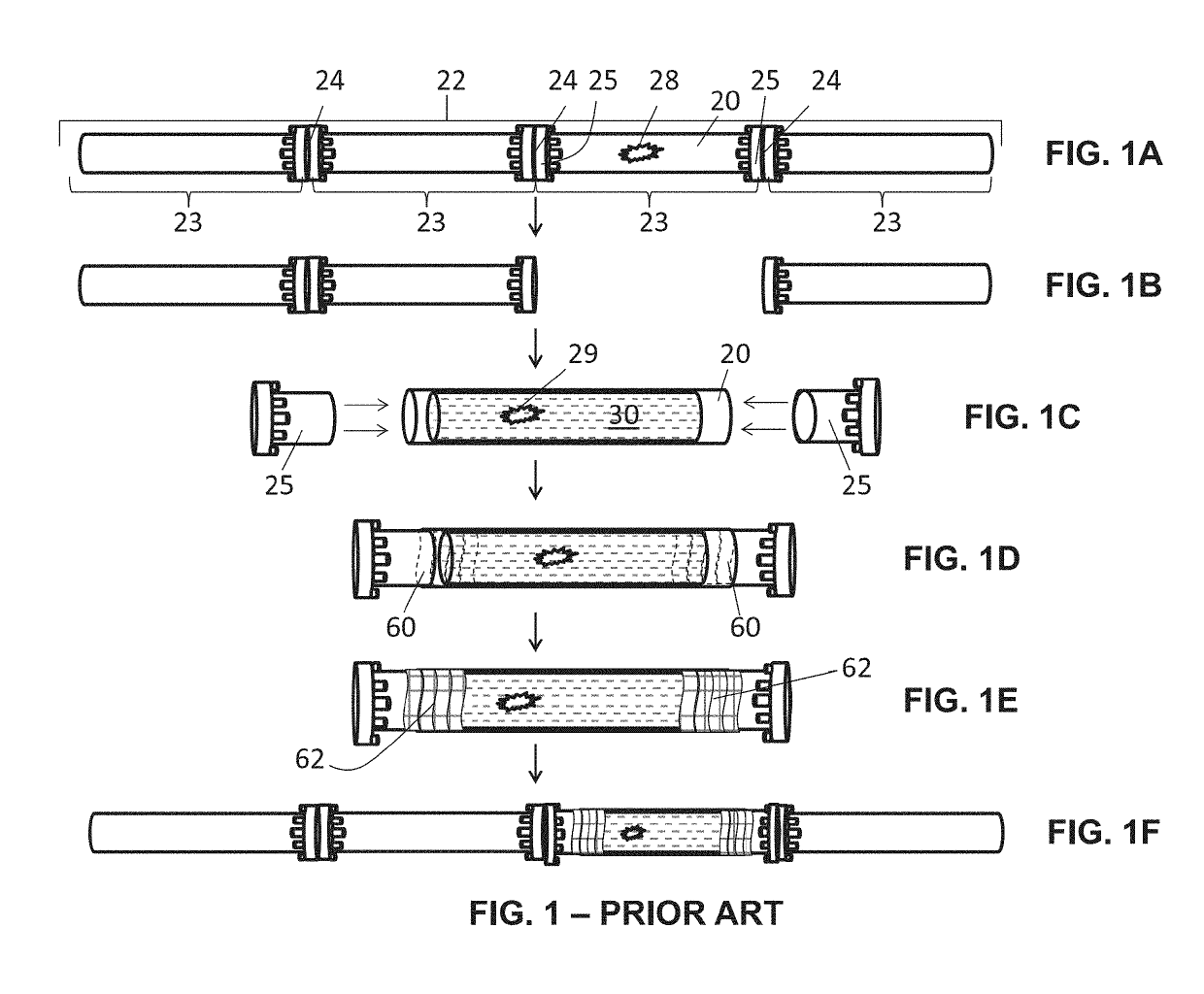
With time and usage these segments become critically deteriorated or damaged and require repair and / or reinforcement.
One issue with CIPP technologies, both conventional and the aforementioned improvement, is the reconnection of a CIPP enhanced host pipe to the existing pipes in a pipeline.
Replacement fittings are difficult to install, and their failure rate is high.
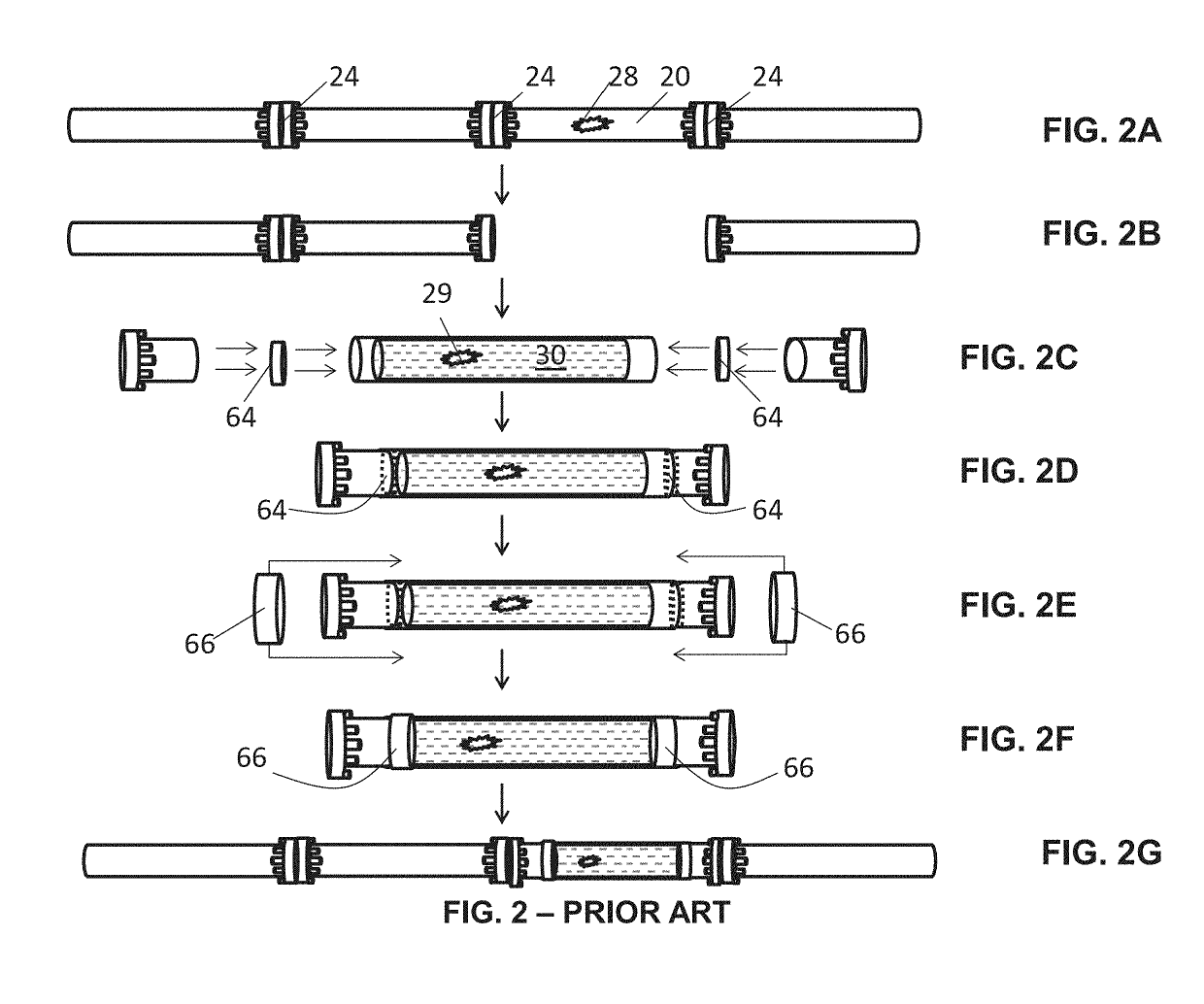
Problems with this technique include difficulty in applying patches and in particular the internal patch, imperfect bonding, deterioration, flow disruption and leaking.
Problems with this technique include difficulty in installation, deterioration, flow disruption and leaking.

Method used


Image

  • Pipe fittings having integrated thermoplastic with improved melt-flow characteristics for cured in place pipe systems and associated method of use
  • Pipe fittings having integrated thermoplastic with improved melt-flow characteristics for cured in place pipe systems and associated method of use
  • Pipe fittings having integrated thermoplastic with improved melt-flow characteristics for cured in place pipe systems and associated method of use

Examples


Embodiment Construction

[0045]The following detailed description is of the best currently contemplated modes of carrying out exemplary embodiments of the invention. The description is not to be taken in a limiting sense, but is made merely for the purpose of illustrating the general principles of the invention, since the scope of the invention is best defined by the appended claims.

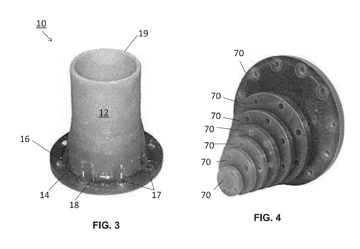
[0046]The following structure numbers shall apply to the following structures among the various FIGS.:[0047]10—Fitting;[0048]12—Tubular extension;[0049]14—Flange;[0050]16—Interface;[0051]17—Apertures;[0052]18—Proximal end;[0053]19—Distal end;[0054]20—Host pipe;[0055]21—Bolts;[0056]22—Pipeline;[0057]23—Pipe segment;[0058]24—Pipe junction;[0059]25—Conventional fitting;[0060]28—Compromised portion;[0061]29—Repaired portion;[0062]30—Cured In Place Pipe (CIPP);[0063]31—Substrate;[0064]32—Fibers;[0065]34—Needle punch;[0066]40—Heater;[0067]42—Air;[0068]60—Internal patch;[0069]62—External patch;[0070]64—Internal band;[0071]66—External b...


PUM

PropertyMeasurementUnit
Temperatureaaaaaaaaaa
Pressureaaaaaaaaaa
Flow rateaaaaaaaaaa

Abstract

A fitting including a tubular extension, flange with apertures, and interface there between is fused with surrounding cured in place pipe and subsequently connected with an adjoining fitting, to connect two segments of pipe in a pipeline. The tubular extension is sized and shaped to mate with the host pipe with which it is associated, and the flange is sized, shaped, and has an aperture pattern that corresponds with the fitting to which it will be attached.

Description

CROSS-REFERENCE TO RELATED APPLICATION[0001]This application claims the priority of U.S. Provisional Patent Application Ser. No. 62 / 630,873, entitled PIPE FITTINGS HAVING INTEGRATED THERMOPLASTIC WITH IMPROVED HELT-FLOW CHARACTERISTICS FOR CURED IN PLACE PIPE SYSTEMS AND ASSOCIATED METHOD OF USE, which was filed Feb. 15, 2018. The aforementioned provisional application is hereby incorporated by reference in its entirety.BACKGROUND OF THE INVENTION[0002]The present invention relates to repairing and reinforcing segments of pipe in pipelines, and more specifically, to cured in place pipe fittings for use with cured in place pipe systems.[0003]Pressure pipe systems are typically constructed of multiple pipe segments with each pipe segment having a pipe fitting at each terminal end. The pipe segments are connected end to end by joining and bolting pipe fittings one to another. With time and usage these segments become critically deteriorated or damaged and require repair and / or reinforc...

Claims


Application Information

Patent Timeline
IPC IPC(8): F16L55/165F16L23/12F16L23/024F16L23/032
CPCF16L55/1654F16L55/1656F16L23/125F16L23/024F16L23/032
Inventor TAYLOR, JOSEPH
Owner INFRASTRUCTURE TECH LLC
Learn More