
Agent for removing halogen gas, method for producing same, method for removing halogen gas with use of same, and system for removing halogen gas

a technology of halogen gas and removing agent, which is applied in the field of removing agent, can solve the problems of material not meeting the requirements of higher removal ability, leakage and diffusion of waste gas, thermal runaway, etc., and achieve the effect of improving the removal ability of harmful gases

Active Publication Date: 2020-01-23
CLARIANT CATALYSTS JAPAN
View PDF0 Cites 1 Cited by
  • Summary
  • Abstract
  • Description
  • Claims
  • Application Information

AI Technical Summary

Benefits of technology

The present invention provides a removing agent that can efficiently remove halogen-based gases, such as those emitted from semiconductor production processes. This improves environmental safety and reduces the risk of pollution. Additionally, the invention provides a removing agent that is highly safe and can handle increased halogen gas emissions. The improved removing ability also reduces the cost of the removing agent and the risk of accidents.

Problems solved by technology

In this case, there are risks of leakage and diffusion of a waste gas caused by e.g. lowering of removing ability of a removing agent column or replacement of columns accompanying said lowering, and therefore, a removing agent with a high removing ability capable of being minimized in frequency of replacement is required.
However, although these materials used in the column such as activated carbon can adsorb a halogen-based gas therein, they cannot decompose the gas, and thus there is a concern that a harmful gas is released from the materials after the disposal thereof and causes problems.
Moreover, there is a risk that the activated carbon reacts with a halogen gas will cause a thermal runaway.
Through this method, the removing performance can be enhanced to a certain extent, but these materials do not sufficiently meet the requirements for higher removing ability.
As described above, though techniques for removing halogen-based gases have been developed, the market needs a removing agent of higher performance at a higher speed than said development speed, and those needs have not actually been satisfied.

Method used


Image

  • Agent for removing halogen gas, method for producing same, method for removing halogen gas with use of same, and system for removing halogen gas
  • Agent for removing halogen gas, method for producing same, method for removing halogen gas with use of same, and system for removing halogen gas
  • Agent for removing halogen gas, method for producing same, method for removing halogen gas with use of same, and system for removing halogen gas

Examples


reference example 1

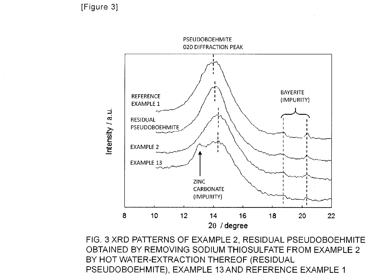
[0103]The process for preparing a sample of Reference Example 1 was undertaken as follows. A shaped body was prepared in the same manner under the same conditions as in Example 1, except that a kneaded cake was obtained by mixing only the pseudoboehmite powder in the grinding machine while water was added thereto. The resulting sample was subjected to the measurement of sulfur atom content, the measurement of tap density and the evaluation of chlorine removing ability at 25° C. by the same methods as in Example 1, and the results are set forth in Table 1.

example 5

[0106]The process for preparing a sample of Example 5 was undertaken as follows. The same shaped body as in Example 2 was prepared in the manner as in Example 2, and then the resulting shaped body was dried overnight in an electric dryer kept at 150° C. The resulting sample was subjected to the measurement of sulfur atom content, the measurement of tap density and the evaluation of chlorine removing ability at 25° C., and the results are set forth in Table 1.

TABLE 1Examples of halogen removing agent comprising pseudoboehmite-thiosulfate, and ReferenceExample and Comparative ExamplesDetection ofSulfursulfurous acidatomTemperaturegas beforeTemperaturecontentfor chlorinedetection ofChlorineMixing ratio amongfor dryinginremovinghydrogenTapremovingraw materialscatalystcatalysttestchloridedensityabilityEx. 190 wt %50° C.2.6 wt %25° C.yes0.86 g / ml16 L / kg pseudoboehmite10 wt % sodiumthiosulfatepentahydrateEx. 282 wt %50° C.4.8 wt %25° C.yes0.89 g / ml20 L / kg pseudoboehmite18 wt % sodiumthiosu...

example 6

[0107]The process for preparing a sample of Example 6 was undertaken as follows. A pseudoboehmite powder, a sodium thiosulfate pentahydrate powder and a magnesium hydroxide powder were weighed in such a manner that the percentage composition by weight of the pseudoboehmite powder, the sodium thiosulfate pentahydrate powder and the magnesium hydroxide powder was 58%, 19% and 23%, respectively, and they were mixed using a grinding machine while water was added thereto, whereby a kneaded cake was obtained. Using a disc pelleter, the kneaded cake was shaped into a particulate shaped body having a diameter of about 2 mm and a length of about 6 mm. The resulting shaped body was dried overnight in an electric dryer kept at 50° C., thereafter placed in a desiccator and held for one hour or more to decrease the temperature to room temperature, whereby a removing agent sample of Example 6 was obtained. The resulting sample was subjected to the measurement of sulfur atom content, the measureme...


PUM

PropertyMeasurementUnit
diametersaaaaaaaaaa
diametersaaaaaaaaaa
temperatureaaaaaaaaaa

Abstract

An agent for removing a halogen gas, such as chlorine, in a waste gas by means of reduction; a method for producing this agent; a method for removing a halogen gas by use of this agent; and a system for removing a halogen gas. The agent for removing the halogen gas contains at least pseudo-boehmite, that serves as a host material, and a sulfur-containing reducing agent, that serves as a guest material. 1-8% by weight of the reducing agent, in terms of elemental sulfur, based on the total amount of the pseudo-boehmite and sulfur-containing reducing agent is present in the agent. At least one inorganic compound selected from among oxides, carbonates salts and hydrocarbon salts of alkaline earth metal elements, transition metal elements and zinc group elements is additionally contained in the agent as a third component.

Description

TECHNICAL FIELD[0001]The present invention relates to a removing agent that allows a halogen-based gas, particularly a halogen-based waste gas arisen from halogen used in / as an etching gas or a cleaning agent in the production process for semiconductors, to efficiently react with a solid oxide to be fixed therein, and thereby prevents re-separation of the waste gas so as to not cause environmental pollution.BACKGROUND ART[0002]Examples of halogen-based gases include F2, Cl2, Br2, ClF3, BrF3 and BrF5, and in a broad sense, many kinds of halogenated non-metallic gases such as SiF4 and BCl3 are also included therein. As methods for removing halogen-based gases, a wet removing method in which a halogen-based gas is removed with a large amount of water in a scrubber, and a dry removing method in which a halogen-based gas is brought into contact with a solid to thereby decompose and fix it in said solid are conventionally known, and in recent years, a dry removing method has been widely u...

Claims


Application Information

Patent Timeline
Patent Type & Authority Applications(United States)
IPC IPC(8): B01J20/08B01J20/04B01J20/06B01J20/28B01J20/30B01D53/68B01D53/82
CPCB01J20/08B01D53/82B01J20/28085B01D2251/20B01J20/28071B01J20/28073B01J20/3014B01J20/3007B01J20/06B01D2253/104B01J20/045B01J20/041B01D53/685B01D2253/1124B01J20/28083B01J20/04B01J20/18B01J20/28B01J20/30B01D2257/2047B01D2257/302B01D2258/0216B01D2257/2042B01D2257/55B01D2257/2045B01D2257/204B01D2257/2027B01D2257/2022B01D2257/2025B01D2253/102B01D53/508B01D2251/304B01D2251/404B01D2251/602B01D2251/604B01D2251/606B01D2253/108B01D2253/308B01D2253/311B01D2251/402B01D2255/20792B01D2251/608B01D53/02B01D53/86B01D53/68B01D2253/1128
Inventor NAKASHIMA, TADAHITOSUNATA, KENICHIROSHIOYA, YASUSHIKIM, HYUN-JOONG
Owner CLARIANT CATALYSTS JAPAN
Learn More