Vertebral stabilisation device

Active Publication Date: 2019-09-05
FAYADA PAUL
View PDF0 Cites 1 Cited by
  • Summary
  • Abstract
  • Description
  • Claims
  • Application Information

AI Technical Summary

Benefits of technology

The invention is a device that connects two vertebrae in the spine with rods that intersect at the middle of the spine. This device allows for a natural movement of the spine in different directions, such as flexion, lateral inclination, and torsion. This movement improves the comfort of patients with spine issues. The device also allows for a controlled movement of the spine to correct any deformations or injuries. The rods used in the device are designed to match the natural architecture of the spine, making them easier to accept by the patient. Overall, the device provides a natural and comfortable movement of the spine while also allowing for controlled stabilization and correction of spine issues.

Problems solved by technology

This blocking reduces the pain that the patient may feel, but it obviously affects the mobility of the patient to the point of being a handicap.

Method used


Image

  • Vertebral stabilisation device
  • Vertebral stabilisation device
  • Vertebral stabilisation device

Examples


first embodiment

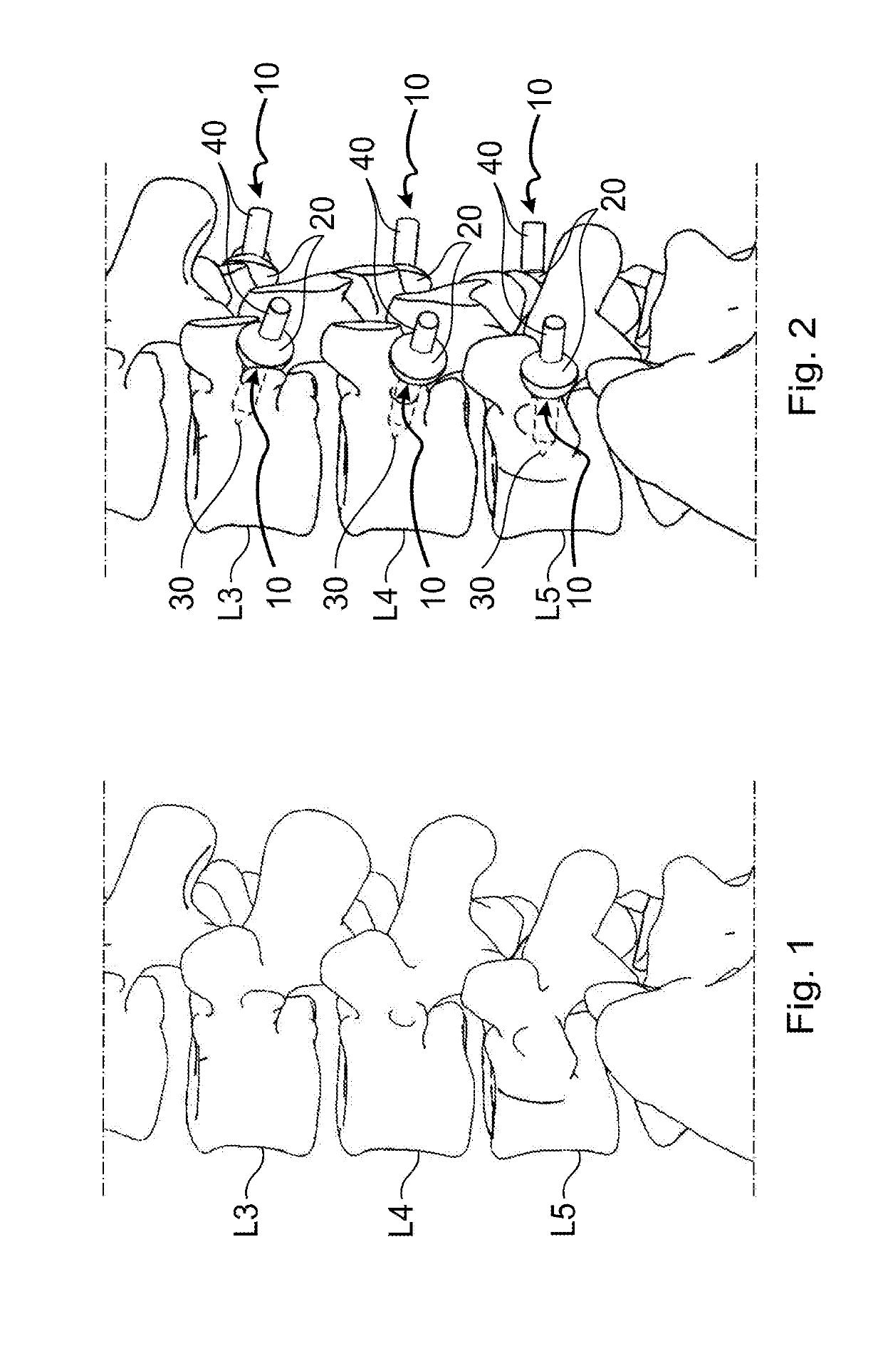
[0031]With reference to FIGS. 1 to 11, the vertebral stabilization device according to the invention comprises pairs of rods 1, forming main linking elements, arranged to connect two separate vertebrae to each other, and attachment elements 10 for attaching the ends of each rod 1 to the two separate vertebrae.

[0032]Each rod 1 extends along a median longitudinal plane containing a longitudinal direction of the rod. The rods 1 have a length, measured in this longitudinal direction, which is such that each rod 1 can extend diagonally between the two vertebrae to which it is attached, intersecting the median sagittal plane S of the vertebral column, the two rods 1 of each pair of rods 1 intersecting substantially at said median sagittal plane S.

[0033]The rods 1 have a curved central portion 2 (the center of curvature being located substantially in the median longitudinal plane), an end portion 3 provided with a ring 4 of substantially circular shape, and an end portion 5 provided with a...

second embodiment

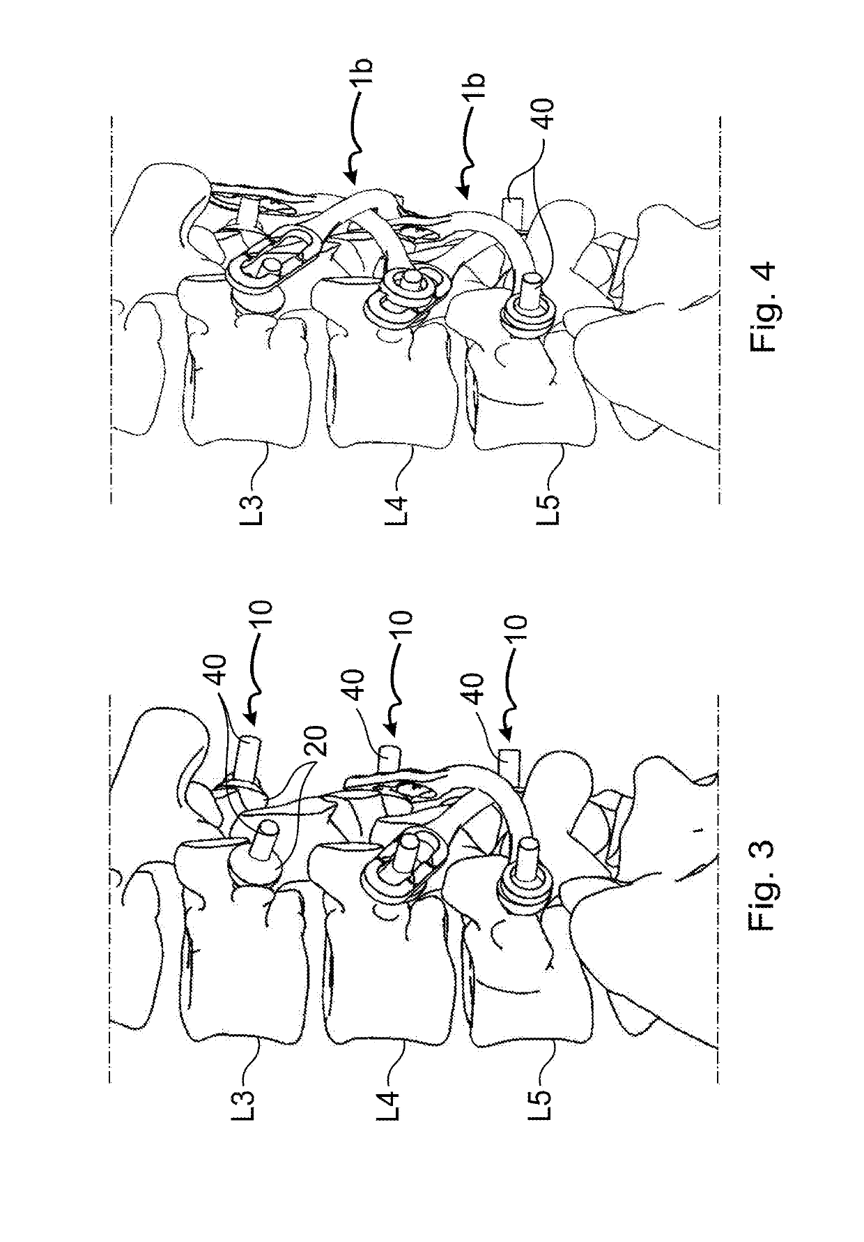
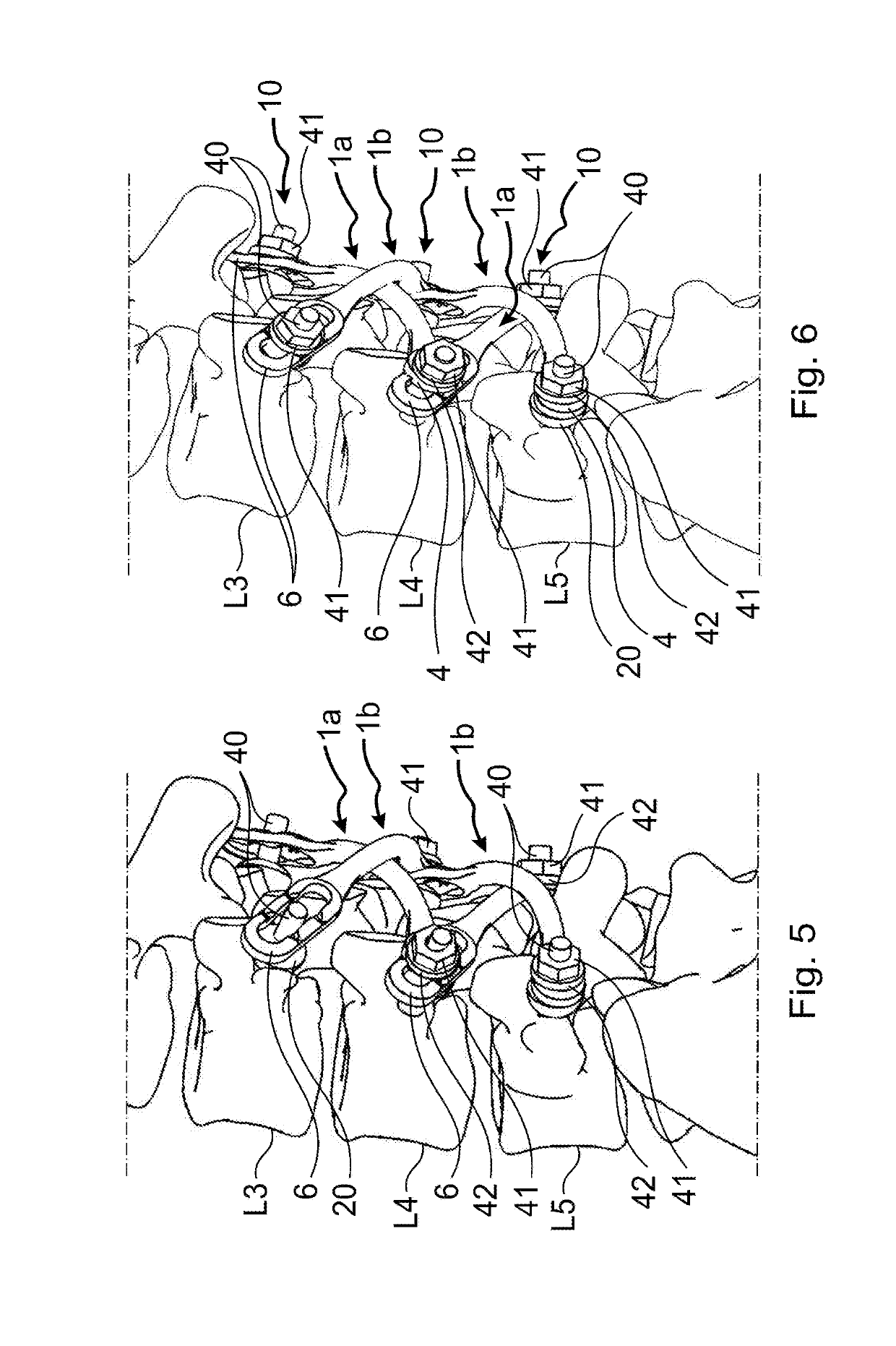
[0058] the rods 1a, 1b each have a curved central portion 2, an end portion 3, and an end portion 5. The end portions 3 and 5 are here of constant cross section and are without a ring or loop.

[0059]Each attachment element 10 comprises a peg and a nut 42 with a base 42, identical to that of the first embodiment.

[0060]The attachment element 10 additionally comprises a body 50 or two bodies 50 depending on whether the attachment element 10 is used to fix one rod or two rods 1.

[0061]The body 50 comprises a tubular portion 51, which defines a seat 52 open along its entire length via a slit 53. From the edges of the slit 53 there extend two plates 54, which are parallel to each other and are separated from each other by a space with a width equal to that of the slit 53. The plates 54 have a hole 55 passing through them and are deformed in order to present a slightly frustoconical shape. The seat 52 has a diameter corresponding substantially to that of the end portions 3, 5, and the hole 5...

third embodiment

[0092]The attachment elements can directly comprise a complete collar arranged to be disposed around a transverse process, in order to fix there an end of at least one rod, instead of a collar formed of several elements, for example as described in the

[0093]The attachment elements can be arranged so as to fix just one rod.

[0094]Although the attachment elements have been described as being in the form of a rod, they can have other forms, The linking elements can be made of a material other than an organic material, for example of a metal such as titanium.

[0095]In one variant, the rods comprise an end portion provided with a ring and a straight end portion, and the attachment elements comprise a body of parallelepipedal shape which is slit along a plane and is provided with two seats for receiving, respectively, the straight end portion and the ring of two rods 1. The seats pass right through along two parallel axes contained in the plane P and corresponding to the direction in which ...


PUM


Abstract

A vertebral stabilisation device, consisting of at least two linking elements arranged to link two separate vertebrae together, and attachment elements for attaching the ends of each linking element to the two separate vertebrae, characterised in that the length of the linking elements and the arrangement of the attachment elements are such that each linking element can extend diagonally between the two vertebrae to which it is attached, intersecting the mean sagittal plane of the vertebral column, the two linking elements intersecting substantially at said plane, and in that at least the attachment elements situated on a same side of the mean sagittal plane of the vertebral column and on separate vertebrae are not attached to each other.

Description

[0001]The present invention relates to the field of surgical implants and more particularly to vertebral stabilization devices that are implanted in the human body for treatment of diseases of the spine.BACKGROUND ART[0002]There are a great many vertebral stabilization devices, of which the common feature is that they are arranged to connect adjacent vertebrae by means of rods or bars that extend substantially on a plane parallel to the median sagittal plane of the vertebral column.[0003]The stabilization obtained is then very effective but leads to a blocking of the movements of the vertebrae relative to each other. This blocking reduces the pain that the patient may feel, but it obviously affects the mobility of the patient to the point of being a handicap.OBJECT OF THE INVENTION[0004]It is an object of the invention to make available a means for stabilizing the vertebral column of a patient and / or for correcting a deformation between vertebrae of the vertebral column, by connecti...

Claims


Application Information

Patent Timeline
IPC IPC(8): A61B17/70
CPCA61B17/7049A61B17/7026A61B2017/7073A61B17/7043A61B17/7058A61B17/7011A61B17/7008A61B17/7019A61B17/7002
Inventor FAYADA, PAUL
Owner FAYADA PAUL
Why Eureka
Try Eureka