

Image heating apparatus
- Summary
- Abstract
- Description
- Claims
- Application Information
AI Technical Summary
Benefits of technology
Problems solved by technology
Method used
Image


Examples
first embodiment
(1) Example of Image Forming Apparatus
[0038]FIG. 1 is a schematic constructional view showing an example of an image forming apparatus to which a fixing apparatus according to the present invention is mounted. This image forming apparatus is a full color printer of tandem type using an electrophotographic process.
[0039] Y, M, C and B denote four (first to fourth) color toner image forming stations arranged from right to left in order in FIG. 1. Each of the stations Y, M, C and B is an electrophotographic processing mechanism comprising an electrophotographic photosensitive member 11 of rotary drum type as an image bearing member, a charging device 12, an exposure device 13 such as a laser scanner or an LED array, a developing device 14 and a cleaning device 15. The photosensitive member 11 is rotatingly driven at a predetermined peripheral speed in a clockwise direction shown by the arrow.
[0040] The first color toner image forming station Y serves to form a toner image including...
second embodiment
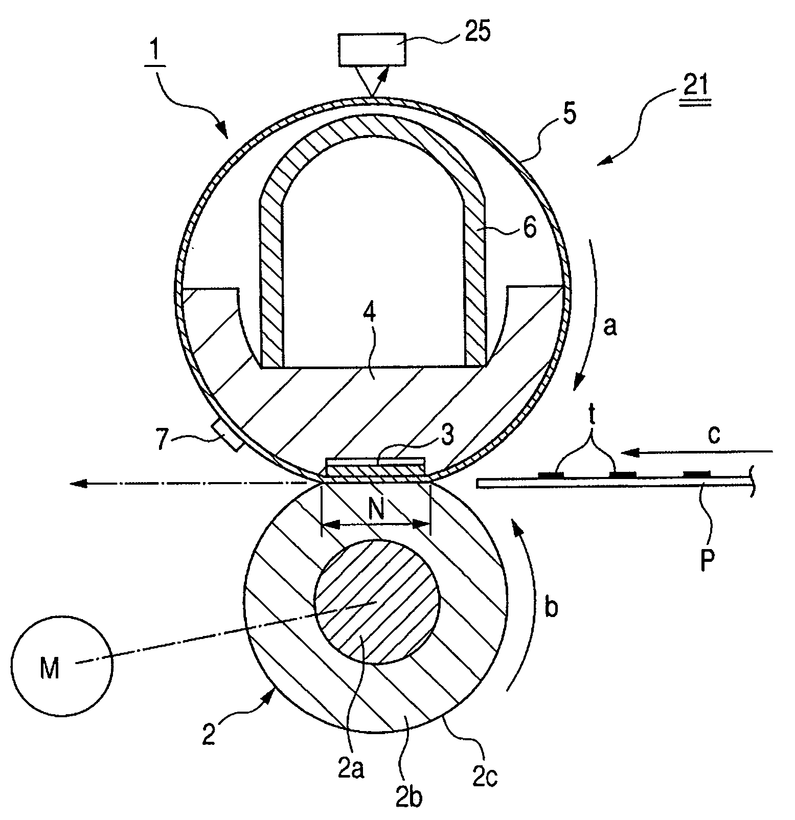
[0094]FIG. 13 is a schematic sectional view of a fixing apparatus 21 of electromagnetic induction heating type according to a second embodiment of the present invention.
(1) Whole Construction of Fixing Apparatus 21
[0095] A fixing belt (laminated belt-shaped heating rotary member; referred to as “belt” hereinafter) 105 is a flexible cylindrical endless belt. The belt 105 has an electromagnetic induction heat generating ability. A layer-structure of the belt will be described later.
[0096] The belt 105 is loosely mounted around a cylindrical thermal insulation stay holder (belt guiding member) 104.
[0097] Magnetic field generating means (heating means for heating the belt) 108 disposed within the thermal insulation stay holder 104 comprises an exciting coil 108a and a T-shaped magnetic core (core member) 108b.
[0098] An elastic pressure roller 102 is urged against a lower surface of the thermal insulation stay holder 104 with the interposition of the belt 105 with predetermined pres...
third embodiment
[0126]FIG. 17 is a schematic sectional view of a fixing apparatus 21 according to a third embodiment of the present invention.
(1) Whole Construction of Fixing Apparatus 21
[0127] Within the fixing apparatus 21, a fixing roller 221 and a heating roller 206 are disposed in parallel with each other and are separated from each other. A flexible endless fixing belt (laminated belt-shaped heating rotary member; referred to as “belt” hereinafter) 205 as an endless belt is wound around the fixing roller 221 and the heating roller 226 in a looped fashion.
[0128] The fixing roller 221 is constituted, for example, by coating a metal core with a soft material such as silicone rubber. In order to increase a contact area between the belt 205 and a pressure roller 202 which will be described later, it is preferable that a heat resistive material having low hardness such as silicone sponge is provided on an outer peripheral surface of the fixing roller 221.
[0129] The heating roller 226 is constit...
PUM
 Abstract
Description
Claims
Application Information