Image forming apparatus

Inactive Publication Date: 2007-06-07
CANON KK
View PDF1 Cites 2 Cited by
  • Summary
  • Abstract
  • Description
  • Claims
  • Application Information

AI Technical Summary

Benefits of technology

[0012] It is an object of the present invention to correct deformations of a belt which are generated at its portions supported by first rollers at the time of stoppage of the belt, with a simple configuration.

Problems solved by technology

However, bending stresses are constantly generated in the endless belt wound around and supported by the tension rollers, at its portions which come into contact with the tension rollers.
However, when the belt is temporarily brought into a standby state, such bending stresses and physical changes are generated concentratively at the portions of the belt which come into contact with the rollers and the heated portion of the belt.
This may cause permanent sets in the belt, thereby causing image degradations such as color shifts, color heterogeneity and the like.
However, if the standby time period becomes longer, this will make it impossible to form images efficiently.
However, if the apparatus is configured to release or reduce the pressures exerted on the belt from the tension rollers at non-operation states of the apparatus as described in the aforementioned Japanese Patent Application Laid-open No. 2003-173090, this will cause the problem of increases of the complicacy and the size of the apparatus.

Method used


Image

  • Image forming apparatus
  • Image forming apparatus
  • Image forming apparatus

Examples


first embodiment

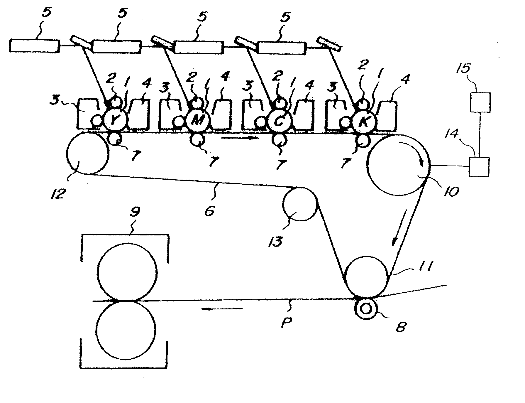
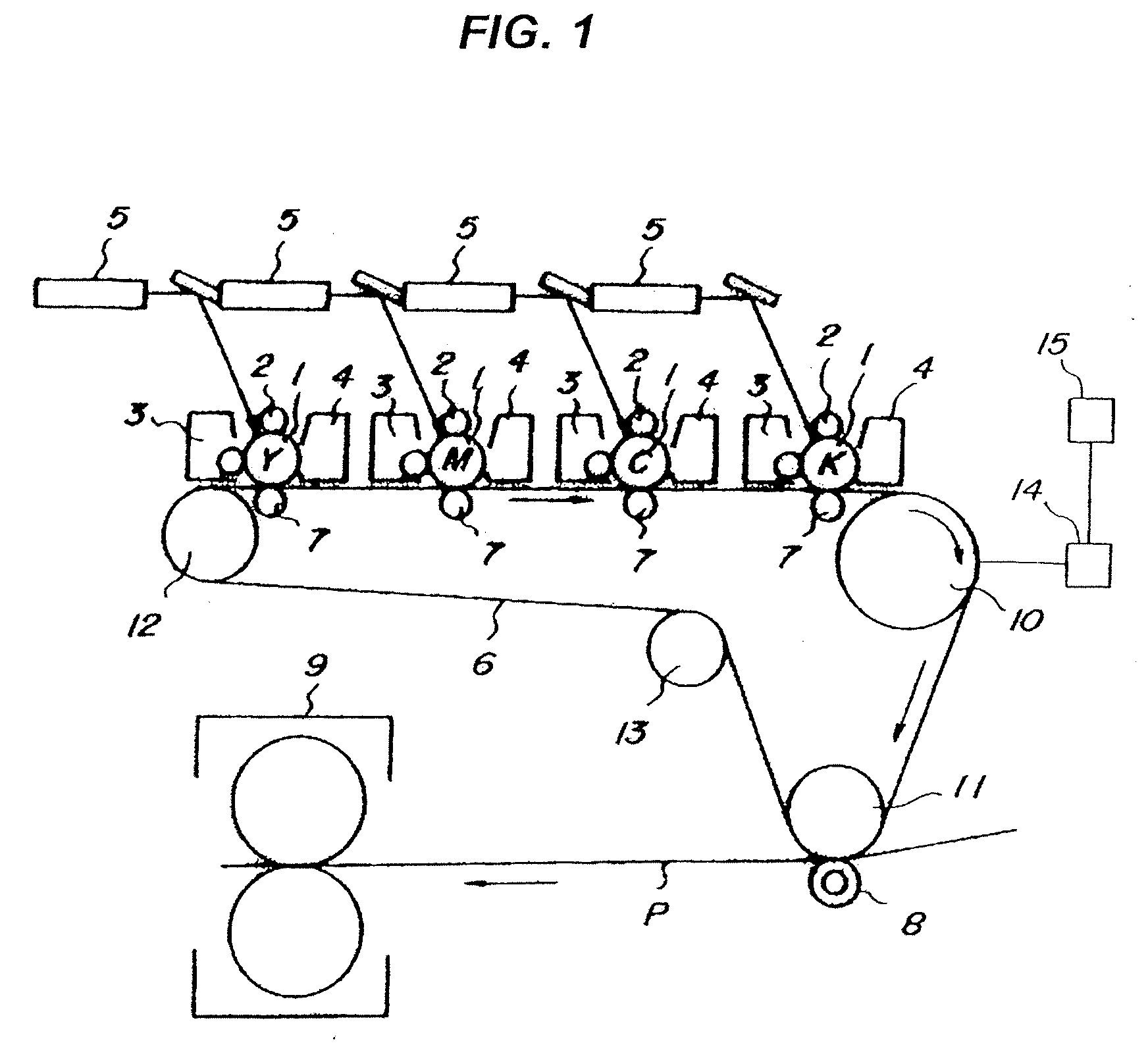
[0026] With reference to FIGS. 1 to 3, there will be described an image forming apparatus according to a first embodiment of the present invention. FIG. 1 is a schematic explanation view of the entire image forming apparatus. FIG. 2 is an explanation view of winding and stringing of an endless belt. FIG. 3 is an explanation view of driving and controlling of the endless belt.

[0027] {The Configuration of the Entire Image Forming Apparatus}

[0028] First, with reference to FIG. 1, the entire configuration of the image forming apparatus will be briefly described, along with operations for forming an image. The image forming apparatus according to the present embodiment forms color images, according to an electrophotographic type.

[0029] An image forming means includes four image forming stations which are placed substantially horizontally, wherein the image forming stations which form toner images in respective colors of yellow Y, magenta M, cyan C and black K are placed in the mentione...

second embodiment

[0061] While, in the aforementioned embodiment, there has been exemplified a case where the belt rotation speed is reduced when the curling-tendency portions α, β and γ of the intermediate transfer belt 6 pass around the counter warping roller 13, it is also possible to drive and control the belt in such a way as to temporarily stop the driving of the belt. For example, the intermediate transfer belt 6 can be stopped for 1 second, when the curling-tendency portions α, β and γ of the intermediate transfer belt 6 pass around the counter warping roller 13.

[0062] With the aforementioned driving and controlling, it is possible to offer effects equivalent to those offered by speed reduction. However, in this case, it is necessary that the curling-tendency portions α, β and γ be wound around the counter warping roller 13 without being protruding therefrom at the time of stoppage of the belt and, therefore, the apparatus is configured such that the amount of winding of the belt around the ...

third embodiment

[0064]FIG. 4 illustrates an image forming apparatus which employs, as a counter warping roller 13, a metal roller internally including a heater 16 which is a heating means. In the present example, a ceramic heater is employed as the heater 16. The image forming apparatus according to the present example has the same configuration as that of the image forming apparatus according to the first embodiment except the counter warping roller 13. Therefore, the components which have the same configurations and effects will be designated by the same reference characters and description thereof will be omitted.

[0065] In the present example, the counter warping roller 13 is heated to 50 degree. C by the heater 16, when the curling-tendency portions pass around the counter warping roller 13 or when the intermediate transfer belt 6 is stopped at states where the curling-tendency portions are wound around the counter warping roller 13. The counter warping roller 13 heats the curling-tendency por...


PUM


Abstract

There is provided an image forming apparatus including a belt which conveys images, first rollers which support the belt and a second roller which supports the aforementioned belt at its surface opposite from the surface supported by the aforementioned first rollers, wherein the image forming apparatus rotates the aforementioned belt at a first speed and rotates the aforementioned belt at a second speed smaller than the aforementioned first speed or stops the aforementioned belt when the portions of the aforementioned belt which have been supported by the aforementioned first rollers at the time of stoppage of the aforementioned belt are supported by the aforementioned second roller, prior to image formation after the stoppage of the aforementioned belt.

Description

BACKGROUND OF THE INVENTION [0001] 1. Field of the Invention [0002] The present invention relates to an image forming apparatus which records, onto recording mediums, images formed with image forming means and also forms images by rotating a belt being supported by rollers. More particularly, the present invention relates to an image forming apparatus including a means for correcting the curling tendency of the belt. [0003] 2. Description of the Related Art [0004] As image forming apparatuses such as copying machines and printers, electrophotographic type image forming apparatuses have been widely used as image forming means. In the present day, apparatuses capable of forming color images have been used as such copying machines. [0005] An electrophotographic type color-image forming apparatus includes plural image forming stations for forming images in respective colors of yellow, magenta, cyan and black which are arranged in parallel and superimposes images formed in the respective...

Claims


Application Information

Patent Timeline
IPC IPC(8): G03G15/01
CPCG03G15/0131G03G2215/0119
Inventor KOJIMA, ETSUJI
Owner CANON KK
Why Eureka
Try Eureka