Calculation method, recording method, optical film, and phase modulation structure

a recording method and phase modulation technology, applied in the direction of hologram nature/properties, optical radiation measurement, instruments, etc., can solve the problems of reducing calculation time, limiting the angle at which the original image is reconstructed, and large amount of time required, so as to reduce calculation time and reduce calculation time. , the effect of reducing the calculation tim

Active Publication Date: 2019-09-26
TOPPAN PRINTING CO LTD
View PDF5 Cites 2 Cited by
  • Summary
  • Abstract
  • Description
  • Claims
  • Application Information

AI Technical Summary

Benefits of technology

[0032]According to the calculation method of the first aspect and the phase modulation structure of the ninth aspect, data to be recorded in the unit blocks of a calculated element region only have to be calculated for the unit blocks included in a representative area without the need of performing calculation for all the unit blocks. Thus, calculation time can be reduced.
[0033]According to the calculation method of the second aspect and the phase modulation structure of the tenth aspect, reconstruction points are arrayed on a quantization grid. Thus, calculation time can be reduced.
[0034]According to the calculation method of the third aspect and the phase modulation structure of the eleventh aspect, all angles formed relative to the line extending from the reconstruction point to the center of the corresponding calculated element region are the same. Thus calculation time can be reduced.
[0035]According to the calculation method of the fourth aspect and the phase modulation structure of the twelfth aspect, the representative area has a shape of an isosceles right triangle. Thus, calculation time can be reduced.

Problems solved by technology

In addition, to calculate a composite hologram with a computer, a large amount of time is required.
This method can reduce calculation time by reducing the number of calculation regions, but unavoidably limits the angle at which the original image is reconstructed, reproducing an image in a different range in the vertical or horizontal direction when actually observed.

Method used


Image

  • Calculation method, recording method, optical film, and phase modulation structure
  • Calculation method, recording method, optical film, and phase modulation structure
  • Calculation method, recording method, optical film, and phase modulation structure

Examples


first embodiment

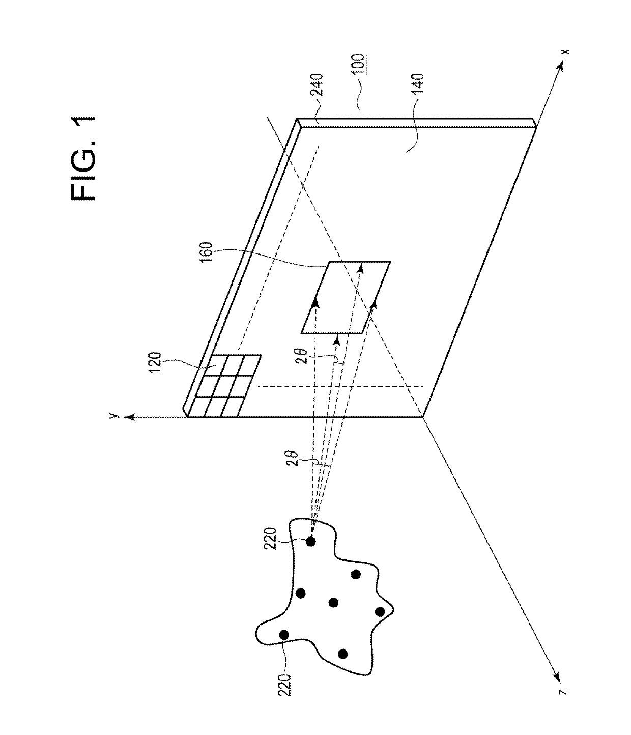
[0076]FIG. 1 is a diagram illustrating an optical film according to a first embodiment of the present disclosure.

[0077]An optical film 100 of the present embodiment includes a recording surface 140 formed of a plurality of unit blocks 120 arranged in a grid pattern on an x-y plane. The recording surface 140 corresponds to a surface of a phase modulation structure 240. The recording surface 140 defines calculated element regions 160 thereon according to viewing angles θ from respective reconstruction points 220 at which an image is reconstructed

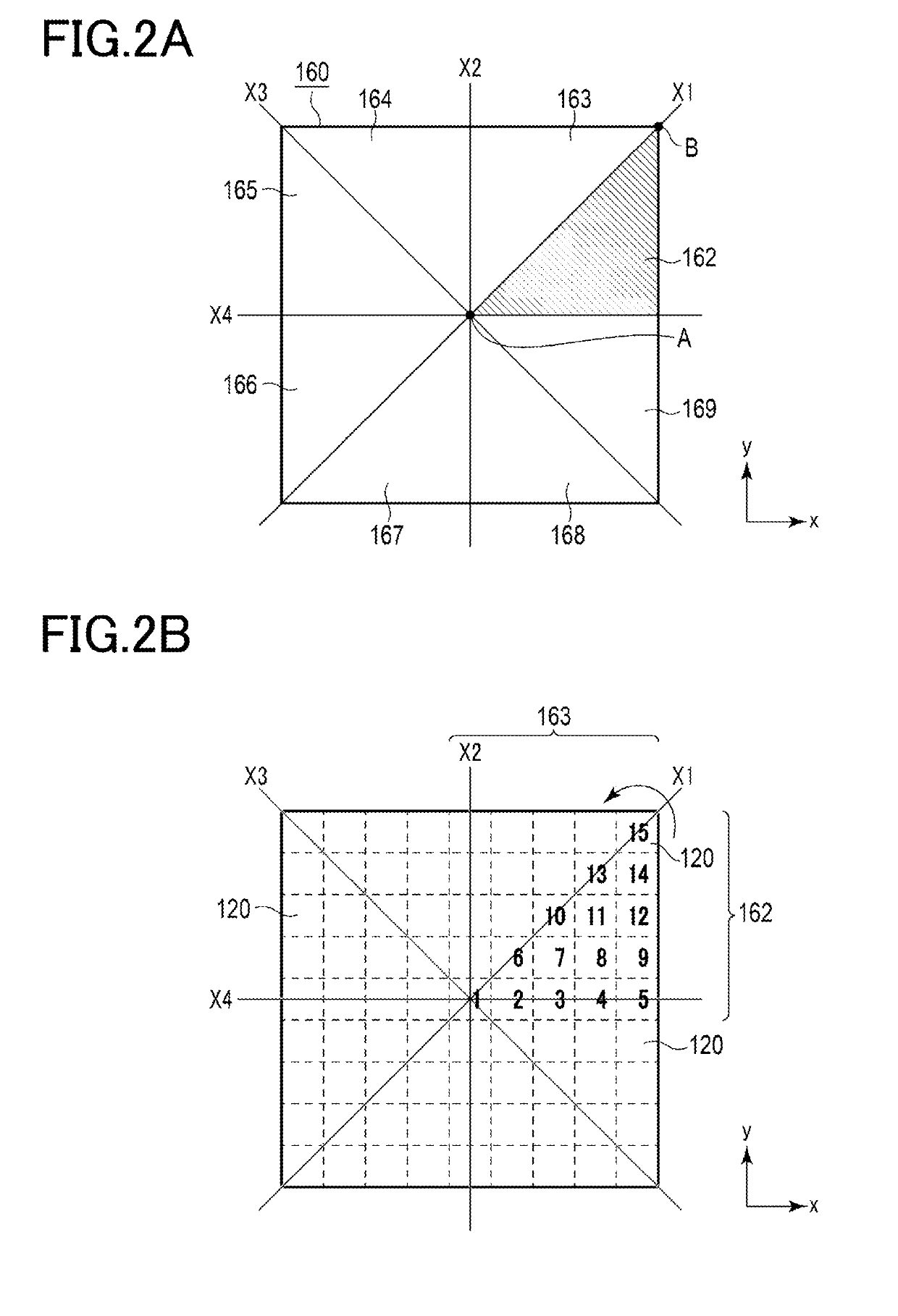
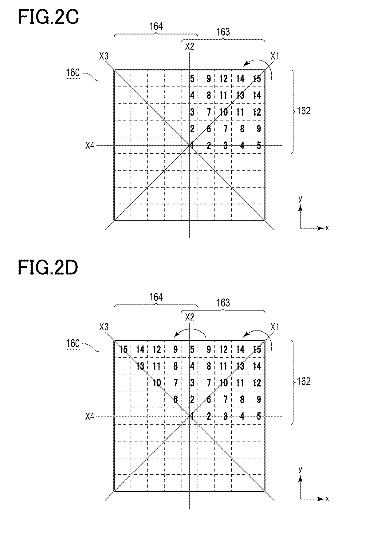
[0078]In each calculated element region 160, a plurality of unit blocks 120 are arranged. Phases of light from the corresponding reconstruction point 220 are calculated in conformity with the locations of the unit blocks 120 in the calculated element region 160 and the calculated phases are used as a basis for calculating phase angles, for recordation in the respective unit blocks. Thus, the calculated element region 160 can be a phase-recordi...

second embodiment

[0118]An optical film according to a second embodiment will be described. In the following description, components having functions identical with or similar to those of the first embodiment are denoted by the same reference signs throughout the drawings to omit duplicate description.

[0119]As described in the first embodiment, numerical information of phase angles ϕ, as data 1 to 15, are recorded in the unit blocks 120. In an optical film 100 of the present embodiment, asperity heights conforming to the phase angles ϕ are reconstructed in the corresponding unit blocks 120, instead of recording numerical information of the phase angles ϕ in the unit blocks 120.

[0120]FIGS. 9A to 9B each show a cross-sectional view of unit blocks 120 in which asperities conforming to phase angles ϕ are formed.

[0121]When converting each phase angle ϕ into an asperity height, the computer calculates the phase angle ϕ in the range of 0π to 2π, and converts the resultant value into an 8-bit grayscale value...

third embodiment

[0147]An optical film according to a third embodiment will be described. In the following description, components having functions identical with or similar to those of the first embodiment are denoted by the same reference signs throughout the drawings to omit duplicate description.

[0148]As described in the first embodiment, numerical information of corresponding phase angles ϕ is recorded in the unit blocks 120. In an optical film 100 of the present embodiment, the computer converts a variation of each phase angle ϕ into a variation in terms of a refractive index of the recording surface 140, instead of recording numerical information of the phase angle ϕ. Furthermore, the computer converts the variation of refractive index into a void realizing the variation. Then, this void 230 is embedded, as shown in FIG. 13, in the substrate 110 at a site of the corresponding unit block 120 to record the phase angle ϕ in the unit block 120.

[0149]As described above, the optical film 100 of the...


PUM


Abstract

A phase modulation structure includes a recording surface including phase angle recording regions in a plurality of calculated element regions corresponding to reconstruction points of an image on a one-to-one basis, each phase angle recording region being formed of a plurality of unit blocks in each of which a phase angle is recorded, the phase angle being calculated based on a phase that is a sum of a plurality of phases of light from the corresponding reconstruction points; and a representative area that is one of divisions of the calculated element region, the representative area being obtained by radially dividing the calculated element region centered on a point on the calculated element region, the point being obtained by extending a normal line from the corresponding reconstruction point to the calculated element region on the recording surface.

Description

CROSS-REFERENCE TO RELATED PATENT APPLICATIONS[0001]This application is a continuation application filed under 35 U.S.C. § 111(a) claiming the benefit under 35 U.S.C. §§ 120 and 365(c) of International Patent Application No. PCT / JP2017 / 045178, filed on Dec. 15, 2017, which is based upon and claims the benefit of priority to and Japanese Patent Application No. 2016-243433, filed on Dec. 15, 2016; the disclosures of which are all incorporated herein by reference in their entireties.TECHNICAL FIELDBackground[0002]The present disclosure relates to a calculation method, a recording method, an optical film, and a phase modulation structure used for recording phases of spatial information calculated by a computer, and applied, for example, to a hologram.Background Art[0003]Optical films in recent years are controlled based on interference of light which is calculated by a computer. For such optical films, the following patent literatures describe a composite hologram calculated by a comput...

Claims


Application Information

Patent Timeline
Patent Type & Authority Applications(United States)
IPC IPC(8): G01J9/02B42D25/328G03H1/00G03H1/08
CPCG01J9/0246G03H1/08G01J2009/0249B42D25/328G03H1/0011G01J2009/0203G03H1/0808G03H1/0244G03H2001/085G03H2001/0825G03H1/0891G03H2001/262G03H2210/452G03H2210/45G03H2224/04G03H2240/42
Inventor KAGOTANI, AKIHITO
Owner TOPPAN PRINTING CO LTD
Why Eureka
Try Eureka