Vehicular lamp

Active Publication Date: 2019-10-03
STANLEY ELECTRIC CO LTD
View PDF5 Cites 0 Cited by
  • Summary
  • Abstract
  • Description
  • Claims
  • Application Information

AI Technical Summary

Benefits of technology

[0027]As described above, according to the presently disclosed subject matter, it is possible to provide a vehicular lamp capable of

Problems solved by technology

However, the leveling adjustment mechanism described in Japanese Patent Application Laid-Open No. 2000-057824 must be configured such that the spherical concave portions are integrally provided on the back side of the reflector, and thus the forming process of the reflector becomes complicated.
However, when the reflector is molded, a sink

Method used


Image

  • Vehicular lamp
  • Vehicular lamp
  • Vehicular lamp

Examples


Embodiment Construction

[0043]A description will now be made below to vehicular lamps of the presently disclosed subject matter with reference to the accompanying drawings in accordance with exemplary embodiments.

[0044]In the drawings used in the following description, in order to make each component easy to be observed, the scale of the dimension may be shown differently depending on the component, and the dimensional ratio of each component is not necessarily the same as the actual ratio.

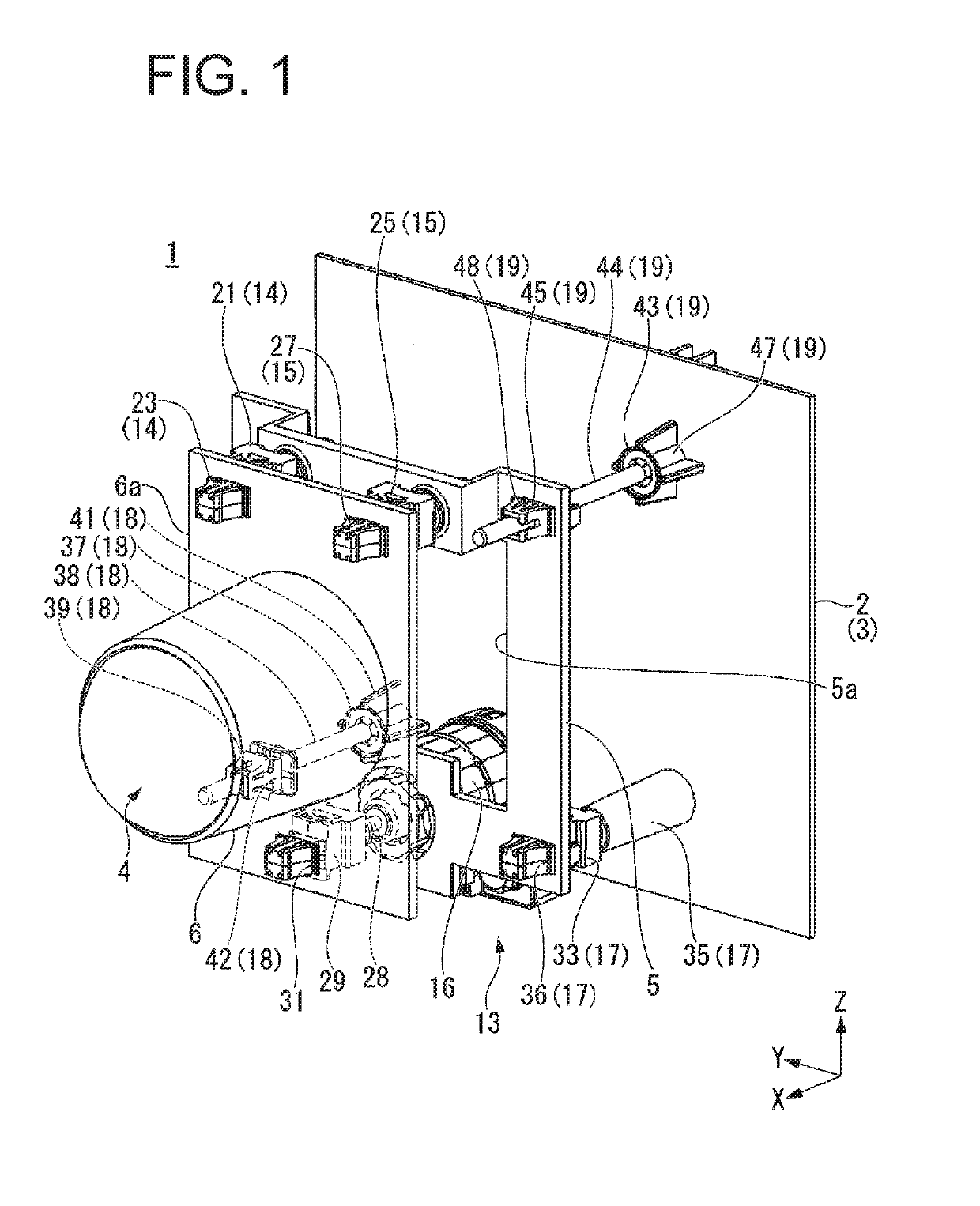
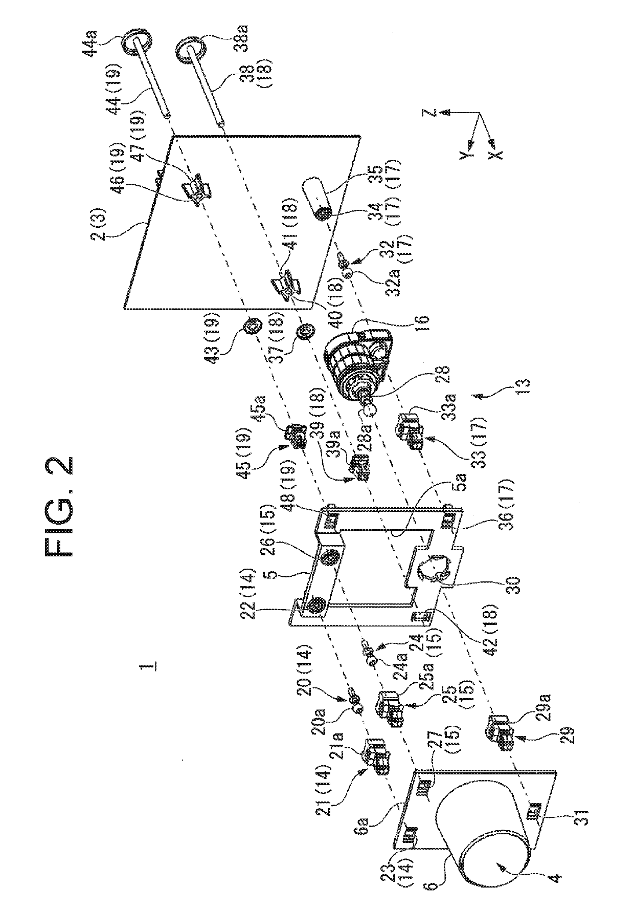
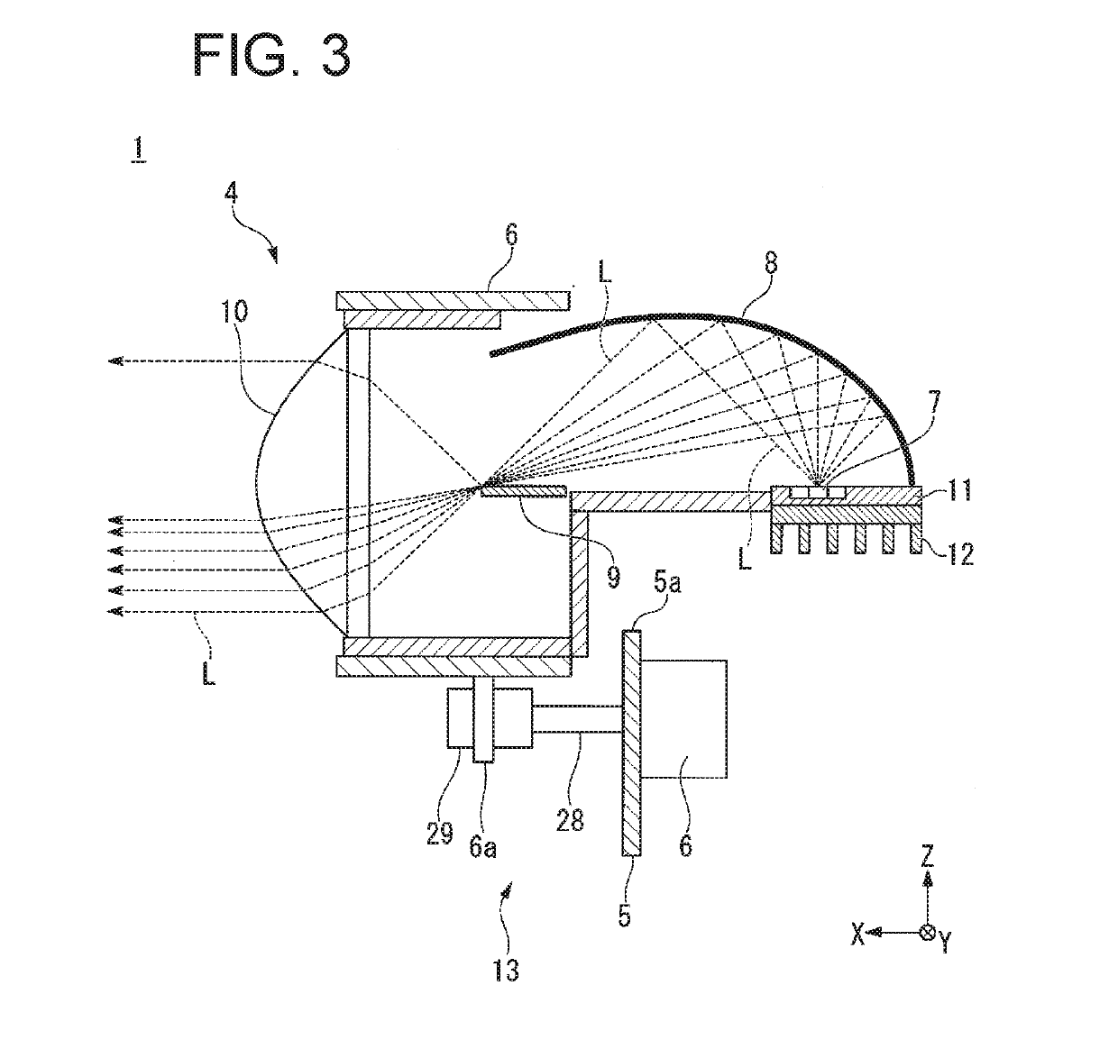
[0045]As an embodiment of the present invention, for example, a vehicular lamp 1 shown in FIGS. 1 to 4 will be described.

[0046]FIG. 1 is a perspective view showing a configuration of the vehicular lamp 1. FIG. 2 is an exploded perspective view showing the configuration of the vehicular lamp 1. FIG. 3 is a side view showing the configuration of the light source unit 4 provided in the vehicular lamp 1. FIG. 4 is a schematic diagram showing the arrangement of support points S1 to S6 when the light source unit 4 provided in ...


PUM


Abstract

A vehicular lamp capable of stably supporting a light source unit and adjusting an optical axis by an optical axis adjusting mechanism is provided. A holder for a light source unit is supported to be tiltable relative to the bracket, and an optical axis adjustment mechanism has three support points supporting the holder relative to the bracket, and includes a first pivot portion located at a first support point among the support points and supporting the holder so that the holder is tiltable relative to the bracket, a second pivot portion located at a second support point and supporting the holder so that the holder is tiltable relative to the bracket, and an actuator located at a third support point and adjusting a tilt of the holder relative to the bracket vertically. In the front view, the first, second, and third support points are located outside the light source unit.

Description

[0001]This application claims the priority benefit under 35 U.S.C. § 119 of Japanese Patent Application No. 2018-062653 filed on Mar. 28, 2018, which is hereby incorporated in its entirety by reference.TECHNICAL FIELD[0002]The presently disclosed subject matter relates to a vehicular lamp.BACKGROUND ART[0003]Conventionally, in a vehicular lamp such as a vehicular headlamp, a light source unit configured to project light toward the front of a vehicle is disposed inside a lamp body constituted by a housing having an opening at its front surface and a lens cover covering the opening of the housing, and an optical axis adjusting mechanism configured to adjust an optical axis of light projected from the light source unit toward the front of the vehicle is provided. Examples of such a vehicular lamp may include those disclosed in Japanese Patent Application Laid-Open No. 2000-057824 (or U.S. Pat. No. 6,220,735 corresponding thereto).[0004]In the vehicular lamp provided with such an optica...

Claims


Application Information

Patent Timeline
IPC IPC(8): B60Q1/076B60Q1/068B60Q1/08
CPCB60Q1/08B60Q1/0683B60Q1/076
Inventor IMAMURA, TOMOYUKI
Owner STANLEY ELECTRIC CO LTD
Why Eureka
Try Eureka