Robot Control Apparatus, Robot, And Robot System
- Summary
- Abstract
- Description
- Claims
- Application Information
AI Technical Summary
Benefits of technology
Problems solved by technology
Method used
Image

Examples
first embodiment
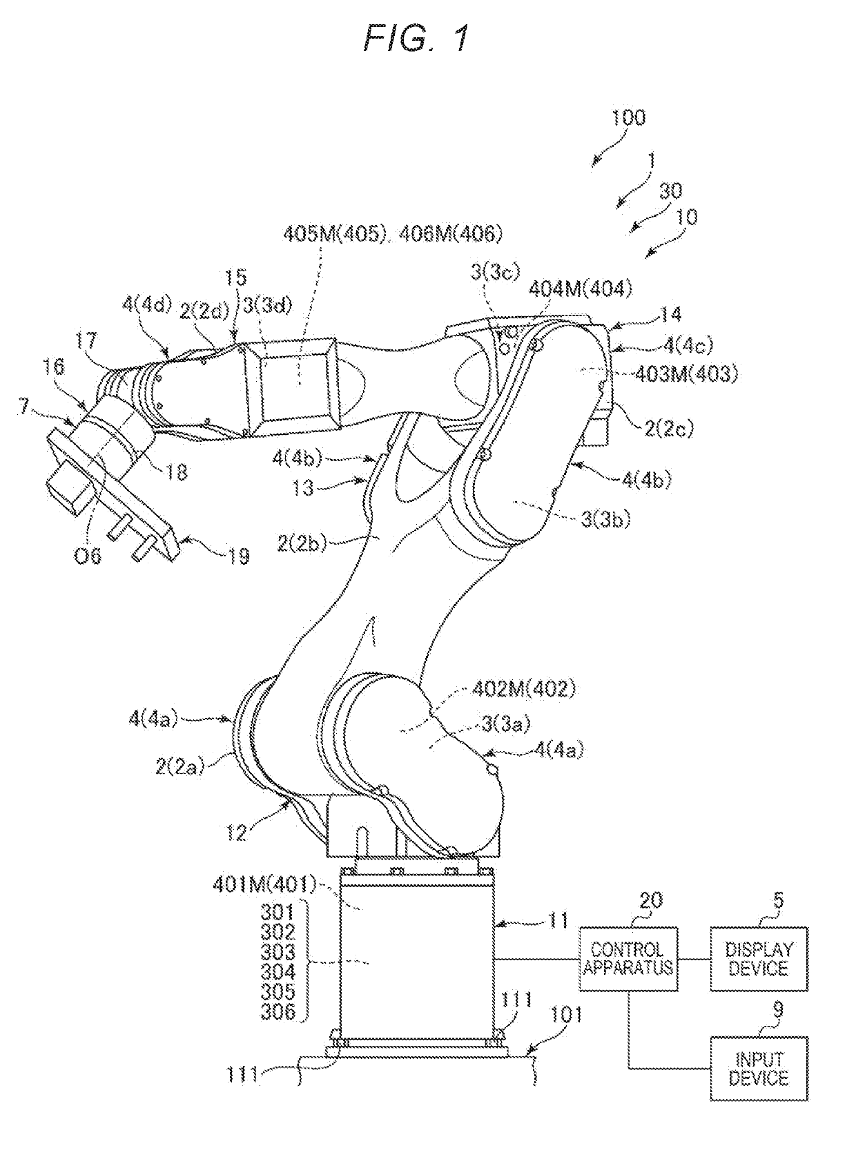
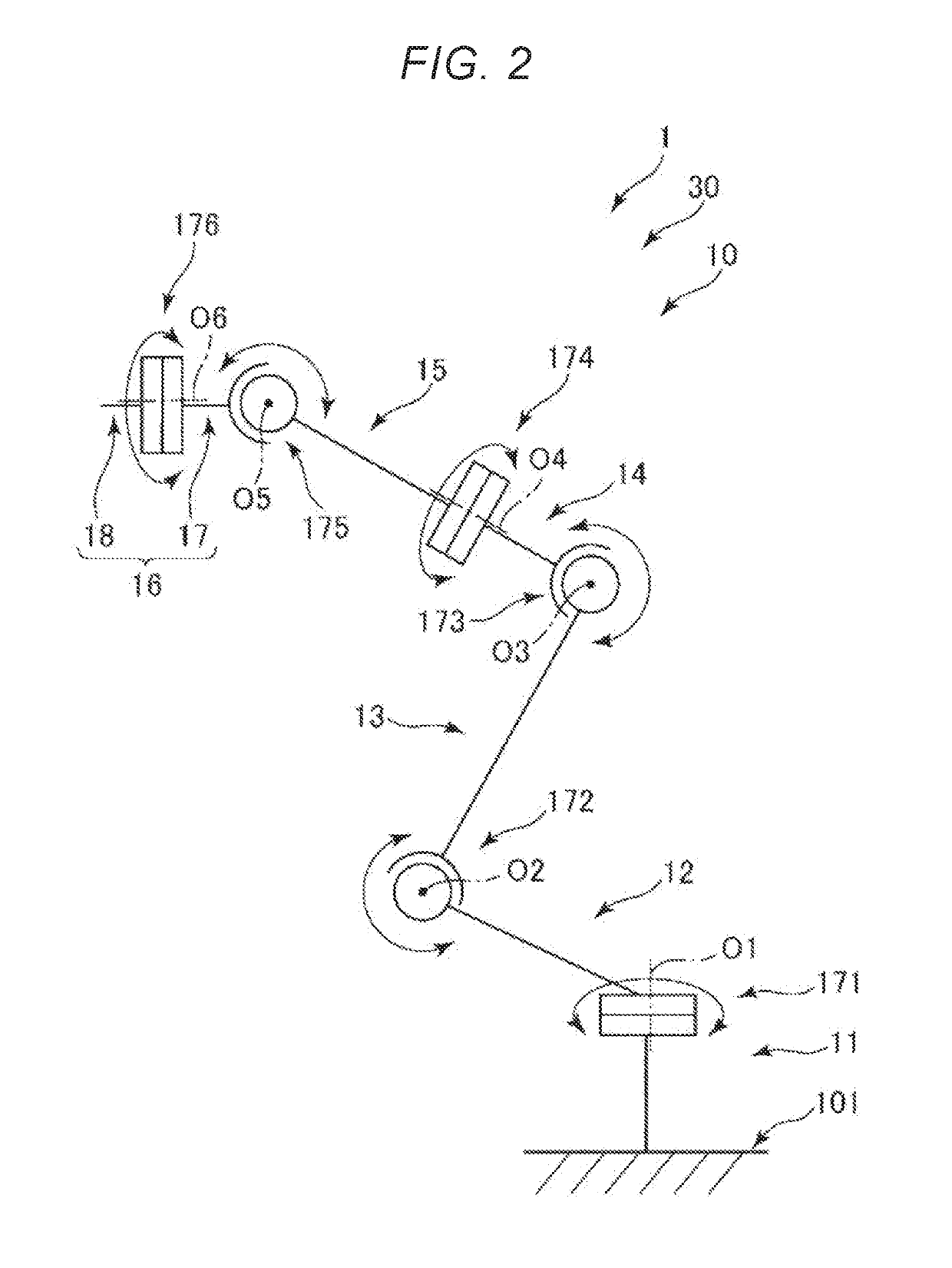
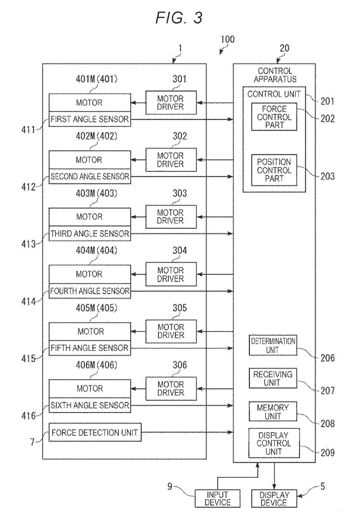
[0040]FIG. 1 is the perspective view (including the block diagram) showing the robot in the first embodiment of the robot system according to the present disclosure. FIG. 2 is the schematic diagram of the robot shown in FIG. 1. FIG. 3 is the block diagram showing the main part of the first embodiment of the robot system according to the present disclosure. FIG. 4 is the perspective view showing the end effector to be attached to the robot shown in FIG. 1. FIG. 5 is an enlarged view of the area [A] surrounded by the dashed-dotted line in FIG. 4. FIG. 6 is the exploded view of the area [A] surrounded by the dashed-dotted line in FIG. 4. FIG. 7 is the exploded view of the area [A] surrounded by the dashed-dotted line in FIG. 4. FIG. 8 is the perspective view of the suction block provided in the end effector shown in FIG. 4. FIG. 9 is the flowchart showing the control operation of the robot control apparatus in the first embodiment of the robot system according to the present disclosure...
second embodiment
[0156]FIG. 19 is the flowchart showing the control operation of the robot control apparatus in the second embodiment of the robot system according to the present disclosure.
[0157]As below, the second embodiment of the robot control apparatus, the robot, and the robot system according to the present disclosure will be explained with reference to the drawing, and the explanation will be made with a focus on the differences from the above described embodiment and the explanation of the same items will be omitted.
[0158]The embodiment is the same as the above described first embodiment except that control by the control apparatus for the coupling work is different.
[0159]As shown in FIG. 19, in the embodiment, when the respective operations (pressing control) of the first operation (step 5101) and the fourth operation (step 5104) are performed, torque control may be executed. The profile control includes the torque control.
[0160]The torque control in the first operation is control of maki...
third embodiment
[0163]FIG. 20 is the flowchart showing the control operation of the robot control apparatus in the third embodiment of the robot system according to the present disclosure.
[0164]As below, the third embodiment of the robot control apparatus, the robot, and the robot system according to the present disclosure will be explained with reference to the drawing, and the explanation will be made with a focus on the differences from the above described embodiments and the explanation of the same items will be omitted.
[0165]The embodiment is the same as the above described first embodiment except that control by the control apparatus for the coupling work is different.
[0166]As shown in FIG. 20, in the embodiment, the control unit 201 of the control apparatus 20 may sequentially control a first operation (step S201), a second operation (step S202), a first inspection (step S203), a third operation (step S204), a fourth operation (step S205), and a second inspection (step S206). Step S201 is th...
PUM
 Abstract
Description
Claims
Application Information