
Folding Hitch

Active Publication Date: 2019-11-28
AGCO INT GMBH
View PDF0 Cites 0 Cited by
  • Summary
  • Abstract
  • Description
  • Claims
  • Application Information

AI Technical Summary

Benefits of technology

The present invention provides a hitch assembly for a working vehicle that can be folded up when not in use, and raised when needed. The hitch assembly includes a carrier, lift arms, and a link member. When in the raised position, the hitch assembly prevents movement about a pivot axis and is locked in place using a locking mechanism. In the folded position, the lift arms can pivot relative to the carrier, and the hitch assembly is secured at a different position using a lock collar or pin. This design reduces the space required for the hitch assembly when folded, allowing the vehicle to operate in smaller environments and increasing the approach angle of the vehicle. The use of a pin or collar for locking the hitch assembly increases reliability and restricts the possibility of misplacement.

Problems solved by technology

When not in use, the lift arms of front hitch assemblies present a hazardous extension of the working vehicle's profile.
Furthermore, the extension of the working vehicle's profile adversely affects the approach and or departure angle of the working vehicle.
However, these can be cumbersome for the operator to change between the transport and operating positions often requiring the detachment and / or lifting of heavy components.
Furthermore, the stowed arms often obstruct the working vehicle lights or other components thus presenting an additional hazard especially when on the road.

Method used


Image

  • Folding Hitch
  • Folding Hitch
  • Folding Hitch

Examples


Embodiment Construction

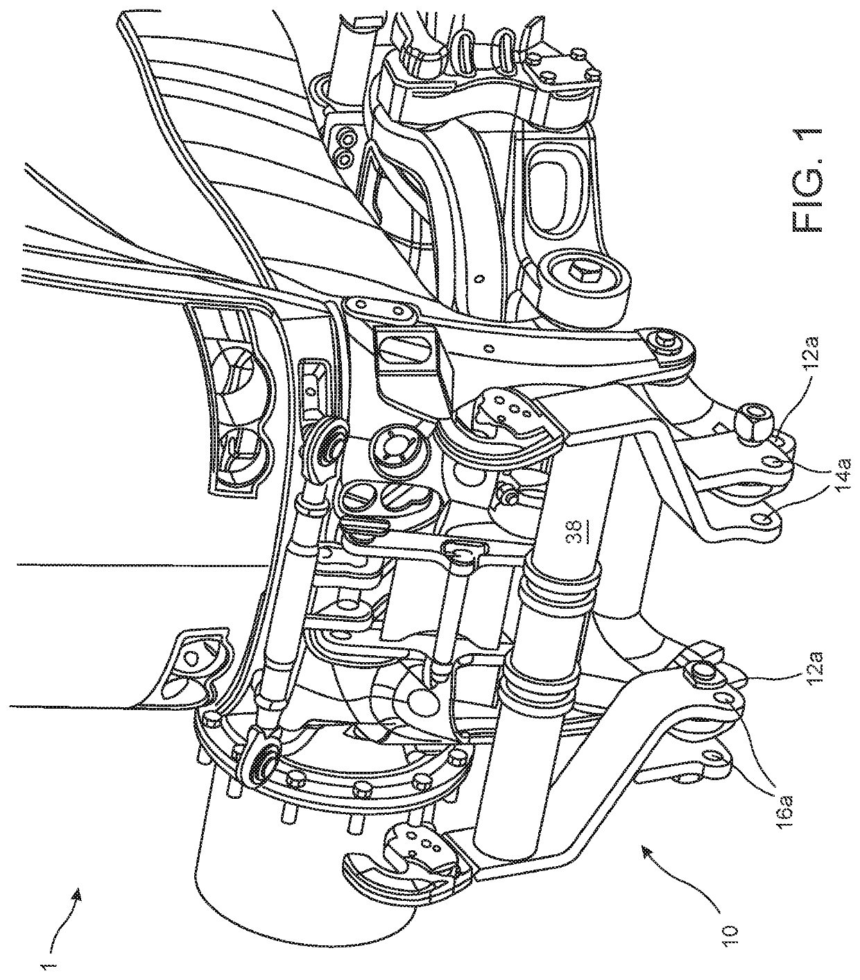
[0021]With reference to FIG. 1, a hitch assembly 10 mounted to the front of a working vehicle 1 which in this example is a tractor.

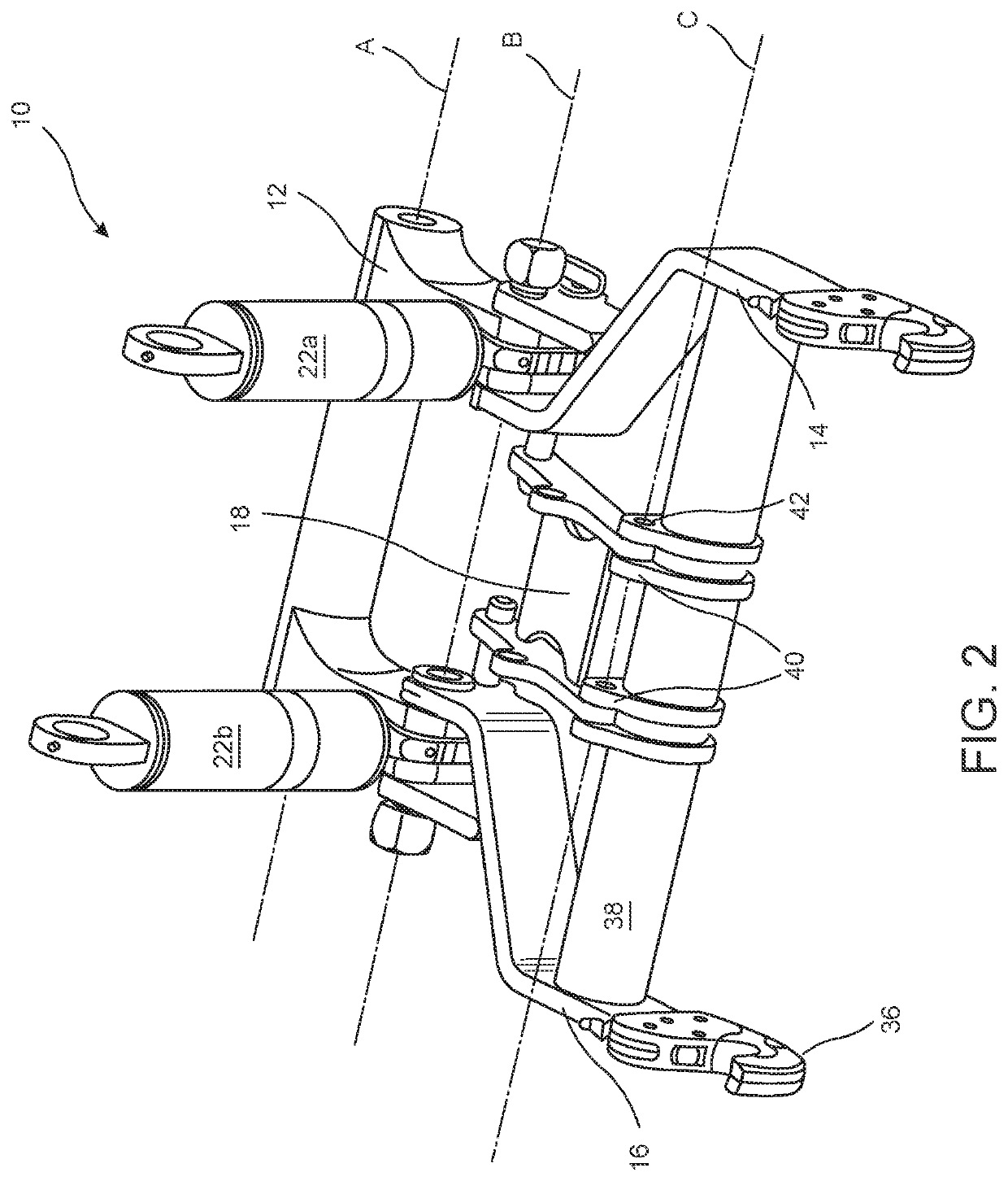
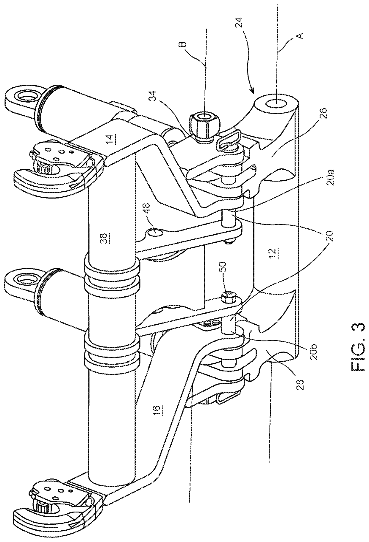
[0022]With reference to FIGS. 1 to 4, the hitch assembly 10 comprises a carrier 12, a pair of lift arms 14, 16, a link member 18, a locking means 20, and a pair of actuators 22a, 22b.

[0023]The carrier 12, is best seen in FIG. 3. The carrier 12 has a generally cylindrical body 24, with two mounting points 26, 28 which project from the body 24. The body 24 is pivotable about an axis A. In this embodiment the axis A denoted where the carrier 12 is pivotable relative to a lower mount 58 which in this case is provided on the vehicle chassis. The carrier 12 further includes a locking hole 12a.

[0024]The pair of lift arms 14, 16, are substantially identical and each have a first end 30 and a second end 32. The first end 30 is forked and has a hinge hole 34 and a locking hole 34. Both the lift arms 14, 16 are pivotable about an axis B. The second end 32 of each...


PUM


Abstract

A hitch assembly for a working vehicle, the front hitch assembly includes a carrier for attachment to a working vehicle, the carrier being pivotable about a first axis; a pair of lift arms each of the lift arms having a first end and a second end, the lift arms pivotably attached to the carrier about a second axis, the second axis being proximate the first ends of the lift arms; a link member having a first end and a second end, the first end of the link member being pivotably attached to the pair of lift arms about a third axis, the third axis being positioned closer to the second end of the lift arms than the second axis, the second end of the link for attachment to a working vehicle; a locking means; an actuator pivotably connected to the carrier and the lift arms at the second axis; wherein the hitch assembly has a working configuration and a folded configuration; and wherein in the working configuration, the locking means secures the lift arms relative to the carrier such that relative movement about the second axis is prevented and the actuator is operable to raise and lower the lift arms; and wherein in the folded configuration, the lift arms are pivotable relative to the carrier about the second axis, and the second end of the link member is secured to a vehicle mount, such that extension of the actuator folds the lift arms relative to the carrier about the second axis, thereby moving the hitch assembly from the working configuration to the folded configuration.

Description

BACKGROUND OF THE INVENTIONField of the Invention[0001]The present invention relates to tractor hitch assemblies which facilitate the attachment of implements to a tractor.Description of Related Art[0002]Implements were traditionally hauled by tractors also known as working vehicles, and attached thereto using either a drawbar or three-point linkage. Today, many large range tractors are fitted with three-point linkages or hitches on both the rear and front to allow two implements to be attached thereby increasing productivity and reducing the number of passes required to work a given area.[0003]Front hitch assemblies inherently protrude forwardly of the main working vehicle frame in order to provide sufficient clearance between implement and working vehicle. Similarly rear hitches protrude rearward from a working vehicle further extending the profile of a working vehicle. When not in use, the lift arms of front hitch assemblies present a hazardous extension of the working vehicle's ...

Claims


Application Information

Patent Timeline
IPC IPC(8): A01B73/04A01B59/06
CPCA01B59/062A01B63/108A01B59/067A01B59/064A01B73/048A01B59/002A01B59/004A01B59/068
Inventor EVRARD, NOEMIEQUONIAM, FRANCOIS
Owner AGCO INT GMBH
Learn More