Seat for vehicle
a seat and vehicle technology, applied in the field of seats for vehicles, can solve the problems of dimensional accuracy that cannot be secured by laser welding, and achieve the effect of improving mass productivity and rigidity of seat back frames
- Summary
- Abstract
- Description
- Claims
- Application Information
AI Technical Summary
Benefits of technology
Problems solved by technology
Method used
Image
Examples
first embodiment
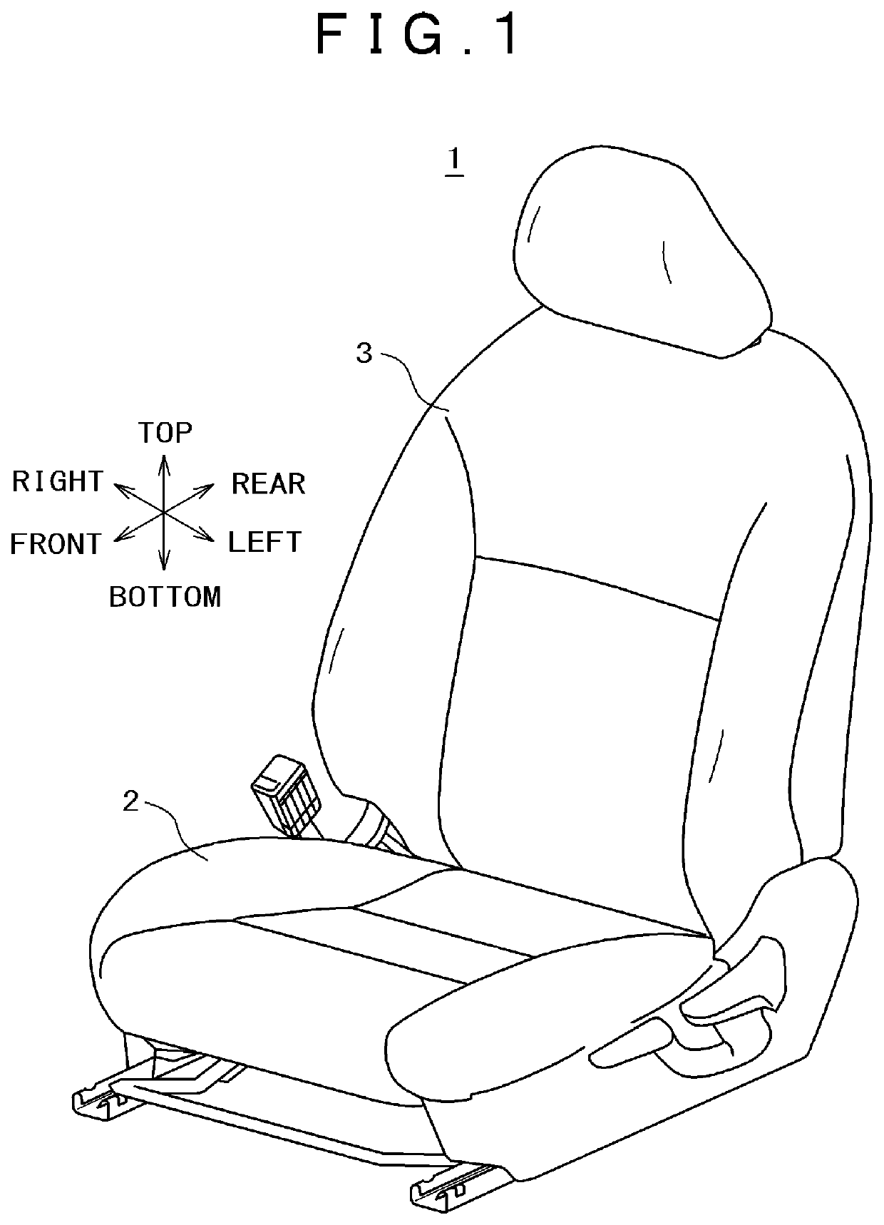
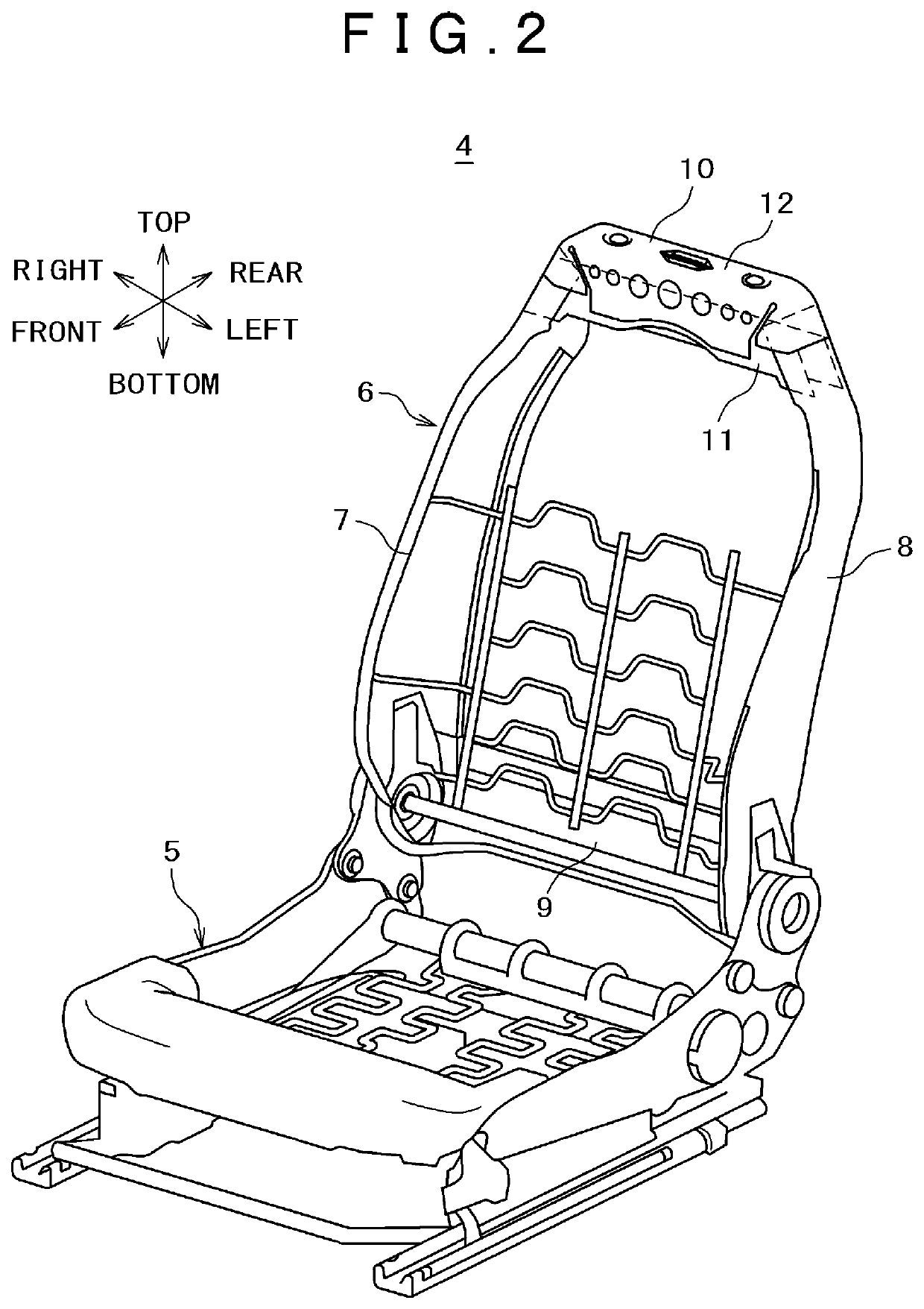
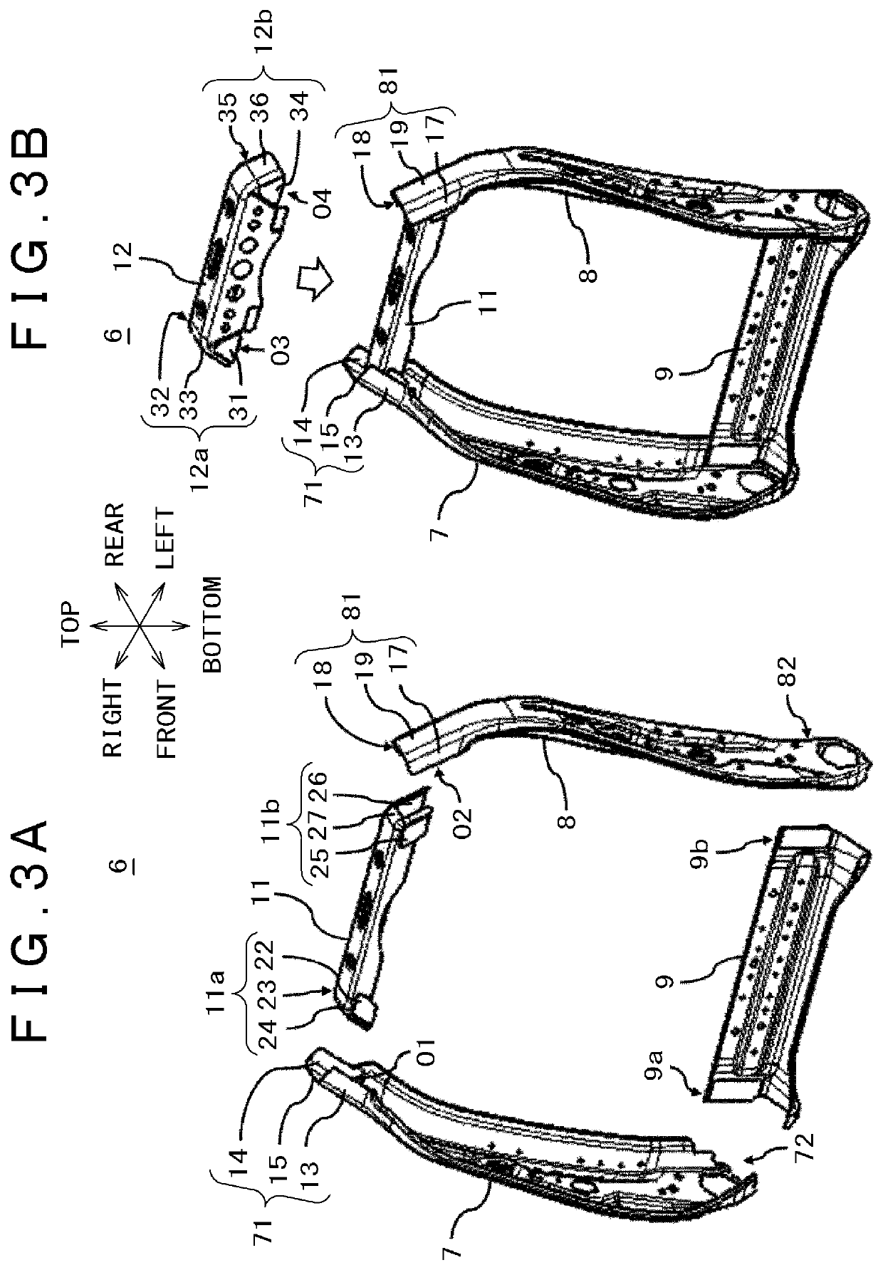
[0026]FIG. 1 is a front perspective view of a seat for vehicle related to the first embodiment. FIG. 2 is a front perspective view of a seat frame of the seat for vehicle shown in FIG. 1. FIG. 3A and FIG. 3B are drawings for explaining a seat back frame, FIG. 3A is a drawing for explaining assembling of left and right side frames, a lower frame, and a first upper frame, and FIG. 3B is a drawing for explaining assembling of a second upper frame. FIG. 4A, FIG. 4B, and FIG. 4C are drawings for explaining assembling of the left and right side frames and the first and second upper frames, FIG. 4A is a front surface enlarged view of the upper part of the seat back frame, FIG. 4B is a cross-sectional view along the line A-A shown in FIG. 4A, and FIG. 4C is a cross-sectional view along the line B-B shown in FIG. 4A. FIG. 5A and FIG. 5B are drawings for explaining a welding position of the left and right side frames and the first and second upper frames, FIG. 5A is a front enlarged view of t...
second embodiment
[0053]The second embodiment has a configuration that, behind the upper frame 10 having a cross-sectional shape of a hat shape, a bracket 40 like a rectangular flat sheet member for example is fixed so as to connect upper and lower flanges (10c, 10d) of the recessed part having a cross-sectional shape of a hat shape, and torsional rigidity of the back frame 6 is improved. Below, the second embodiment will be explained using FIG. 6A, FIG. 6B, FIG. 7A, and FIG. 7B. Further, although the bracket 40 is shown illustratively as a rectangular flat sheet member, it only has to be a fixing member that can connect the upper and lower flanges (10c, 10d) of the recessed part having a cross-sectional shape of a hat shape.
[0054]FIG. 6A and FIG. 6B are drawings for explaining the back frame 6 related to the second embodiment, FIG. 6A is a drawing for explaining assembling of the left and right side frames, the lower frame, the upper frame, and the bracket, and FIG. 6B is a front perspective view of...
PUM
 Abstract
Description
Claims
Application Information
 - R&D
- Intellectual Property
- Life Sciences
- Materials
- Tech Scout
- Unparalleled Data Quality
- Higher Quality Content
- 60% Fewer Hallucinations
Browse by: Latest US Patents, China's latest patents, Technical Efficacy Thesaurus, Application Domain, Technology Topic, Popular Technical Reports.
© 2025 PatSnap. All rights reserved.Legal|Privacy policy|Modern Slavery Act Transparency Statement|Sitemap|About US| Contact US: help@patsnap.com


