Metal catalyst support, manufacturing method and apparatus therefor

Active Publication Date: 2019-12-19
AMOGREENTECH CO LTD
View PDF11 Cites 0 Cited by
  • Summary
  • Abstract
  • Description
  • Claims
  • Application Information

AI Technical Summary

Benefits of technology

[0022]As described above, according to the present disclosure, deformation during thermal expansion due to external impact, vibration, and temperature change can be minimized by making vertexes of laminated corrugated plates face and coincide with each other.
[0023]In addition, convex portions and concave portions are formed at vertexes of corrugated plates, respectively and concavo-convex portions are formed in the flat plates so that the convex portio

Problems solved by technology

Pollutants such as nitrogen oxides, sulfur oxides, carbon monoxide, and hydrocarbons contained in exhaust gas are a great threat to the human environment.
Korean Patent Application Publication No. 10-2012-0117426 discloses a structure in which a large-capacity catalyst support is manufactured in the form of a unit catalyst support block and then assembled, but has a complicated structure having a lot of fastening points in which an assembly member is an element center for being engaged bet

Method used


Image

  • Metal catalyst support, manufacturing method and apparatus therefor
  • Metal catalyst support, manufacturing method and apparatus therefor
  • Metal catalyst support, manufacturing method and apparatus therefor

Examples


Example

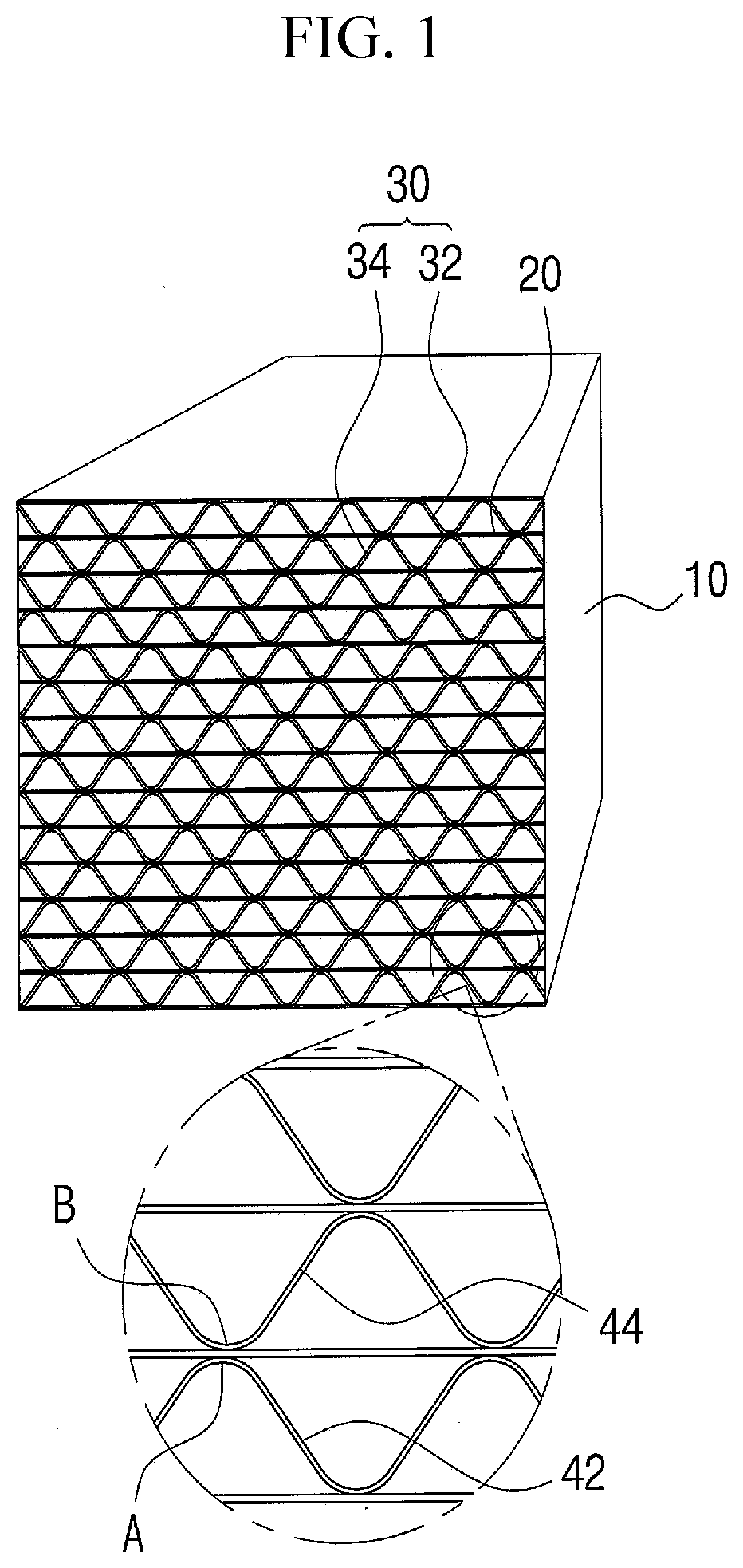
[0031]Referring to FIG. 1, a metal catalyst support according to a first embodiment of the present invention includes: a case 10 of which both sides are opened; and flat plates 20 and corrugated plates 30 which are alternately stacked in the case 10.

[0032]The metal catalyst support is installed in an engine or furnace of a ship, a power plant or a large plant such as an incinerator, and is configured to generate nitrogen and water through reduction reaction of exhaust gas mixed with nitrogen oxide (NOx) and ammonia (NH3).

[0033]The catalyst support is disposed between the exhaust pipes, and a large-capacity catalyst support for supporting the catalyst therein may be disposed in a multi-stage or single-stage configuration.

[0034]The case 10 has a square shape with both open ends, and both ends thereof are connected to an exhaust pipe. The flat plates 20 and the corrugated plates 30 are formed of a heat-resistant thin metal plate, and have the thickness of preferably 20 μm to 100 μm.

[00...

Example

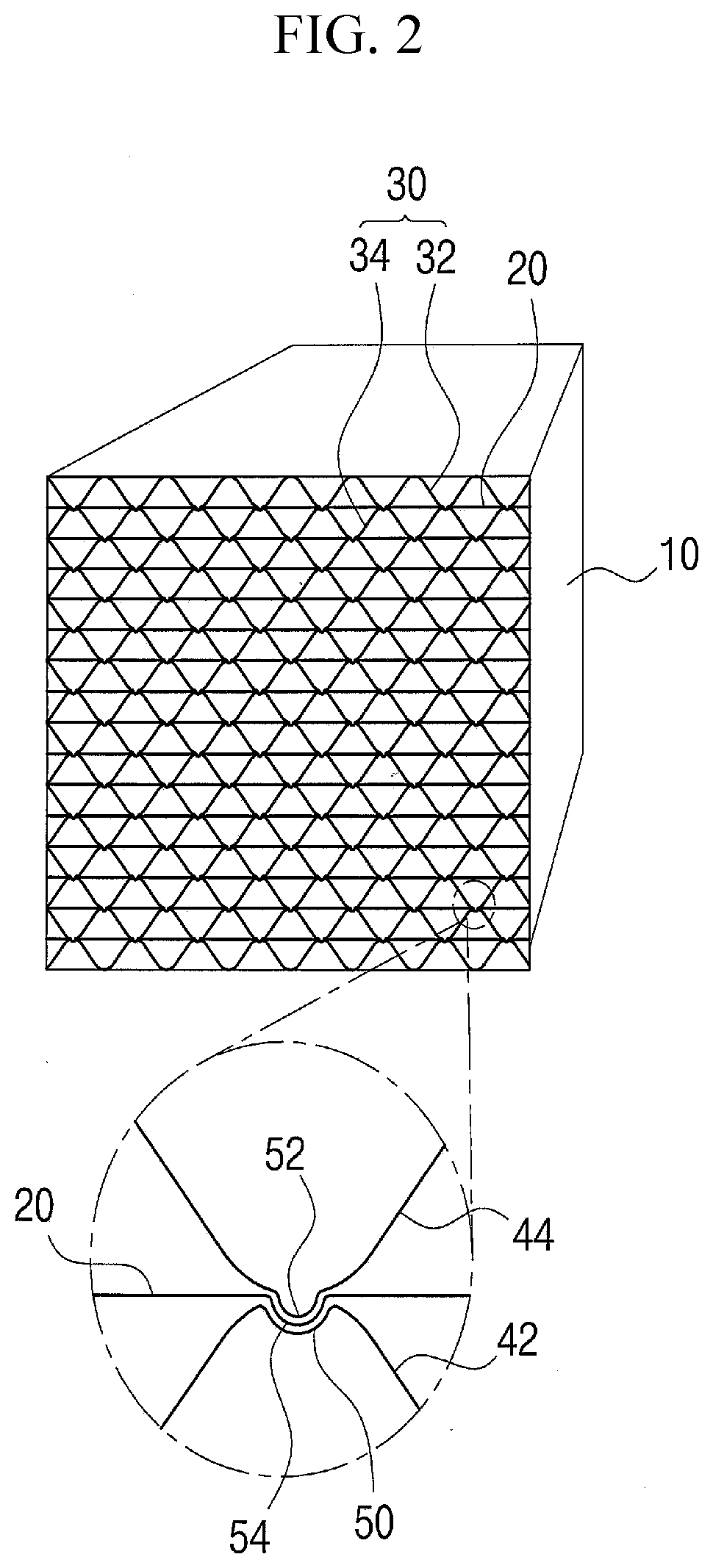
[0039]As shown in FIG. 2, the metal catalyst support according to the second embodiment has a concave portion 50 formed in the longitudinal direction at the vertex of the first corrugated portion 42 of the corrugated plate 30, a convex portion 52 formed in the longitudinal direction at the vertex of the concave portion 44, and a concavo-convex portion 54 formed in the flat plate 20 at a position where the convex portion 52 and the concave portion 50 meet.

[0040]Therefore, when the first corrugated plates 32, the flat plates 20 and the second corrugated plates 34 are alternately stacked, the concave-convex portion 54 of the flat plate 20 is inserted into the concave portion 50 of the first corrugated plate 32, and the convex portion 52 of the second corrugated plate 44 is inserted into the concave-convex portion 54 of the flat plate 20. Thus, the first corrugated plate 32, the flat plate 20, and the second corrugated plates 34 are mutually engaged with each other, so that the corrugat...


PUM

PropertyMeasurementUnit
Temperatureaaaaaaaaaa
Sizeaaaaaaaaaa
Thermal expansion coefficientaaaaaaaaaa

Abstract

Provided is a metal catalyst support including: a case having a space through which exhaust gas passes; and flat plates and corrugated plates which are alternately stacked in the case and coated with a catalyst, wherein the corrugated plates are formed such that a first corrugated plate and a second corrugated plate are disposed with the flat plate therebetween, the first corrugated plate and the second corrugated plate are disposed such that a first corrugated portion and a second corrugated portion are alternately and repeatedly formed, and the vertex of the first corrugated portion and the vertex of the second corrugated portion face and coincide with each other, to thereby minimize deformation during thermal expansion due to external impact, vibration and temperature change.

Description

TECHNICAL FIELD[0001]The present disclosure relates to a metal catalyst support in which vertexes of corrugated plates to be laminated with each other coincide with each other, a manufacturing method thereof, and an apparatus for manufacturing the same.BACKGROUND ART[0002]Pollutants such as nitrogen oxides, sulfur oxides, carbon monoxide, and hydrocarbons contained in exhaust gas are a great threat to the human environment. Countries are also strengthening regulations on harmful exhaust gas or accelerating the development of technologies for reducing harmful emissions.[0003]Automobiles with the largest emissions have a direct impact on the on-the-ground environment in which humans live. As a result, regulatory demands have been high and treatment technologies have been advancing early. However, regulation of exhaust gas of ships has been relatively recently started and International Maritime Organization (IMO) and advanced countries are actively preparing countermeasures.[0004]In th...

Claims


Application Information

Patent Timeline
IPC IPC(8): B01D53/88B32B3/28B32B15/01B32B37/18B32B38/18B21D13/04B21D43/02B01J35/02
CPCB01D2257/302B32B15/01B21D13/04B32B3/28B21D43/02B32B2250/42B01D2257/404B32B2311/00B32B2255/06B01D2257/702B32B37/18B01J35/02B32B38/1808B32B2307/724B01D2257/502B01D53/885B21D53/88B32B37/0076B32B38/1841B32B38/0012B21D43/021B01J35/04
Inventor KIM, MYOUNG SOOKIM, TONG BOK
Owner AMOGREENTECH CO LTD
Why Eureka
Try Eureka