Electric motor

Active Publication Date: 2016-06-30
JOHNSON ELECTRIC INTERNATIONAL AG +1
View PDF7 Cites 3 Cited by
  • Summary
  • Abstract
  • Description
  • Claims
  • Application Information

AI Technical Summary

Benefits of technology

[0019]In comparison with the conventional stator structure, projections and recesses are formed on the outer periphery of the yoke part of the stator core. The projections and recesses are alternately arranged in the axial direction of the stator core. In assembly of the stator core into the housing body, the projections deform into

Problems solved by technology

However, glue may deteriorate over time.
This produces a strong connection but it is not production friendly and, as the size of the stator core and the housing is

Method used


Image

  • Electric motor
  • Electric motor
  • Electric motor

Examples


Example

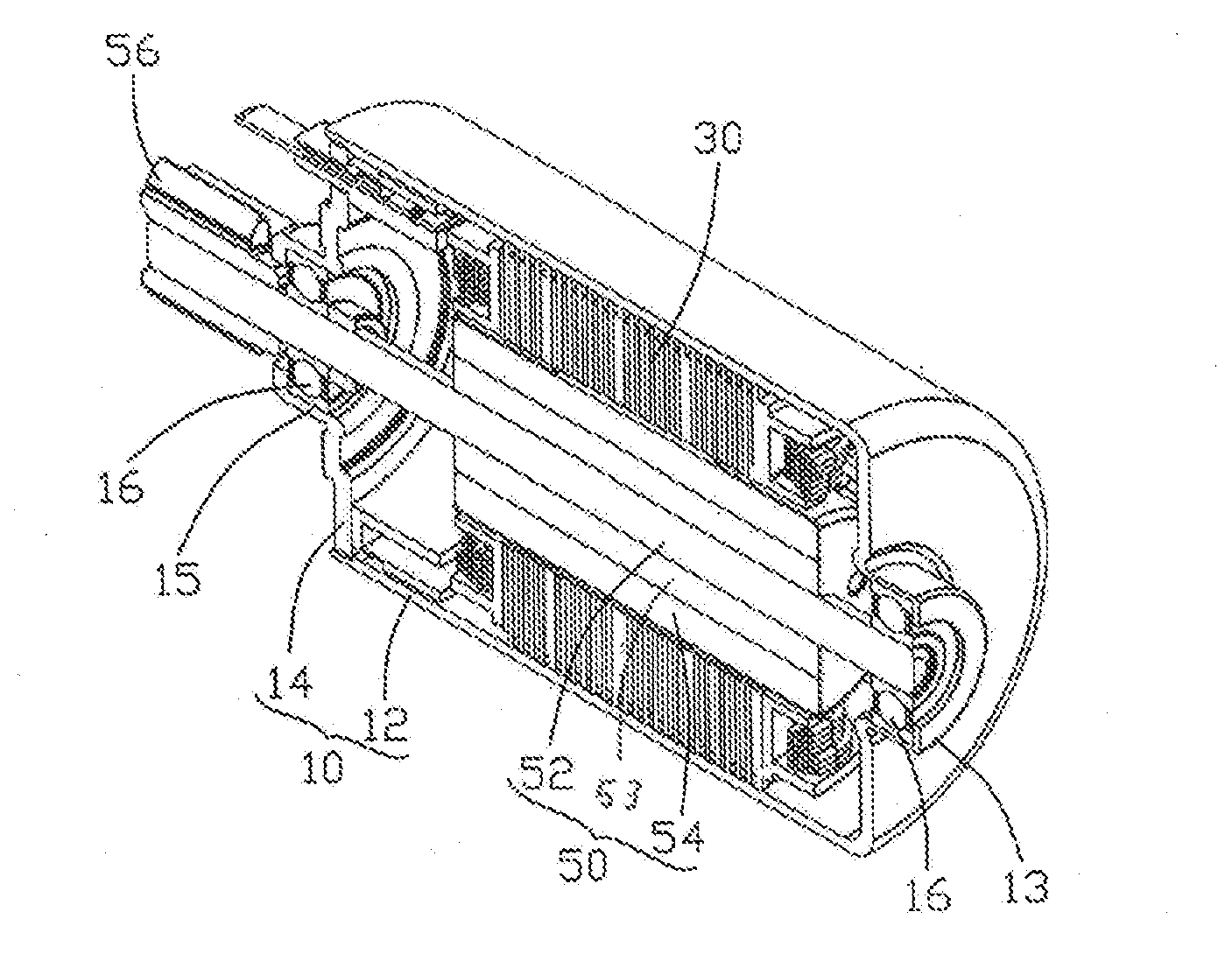
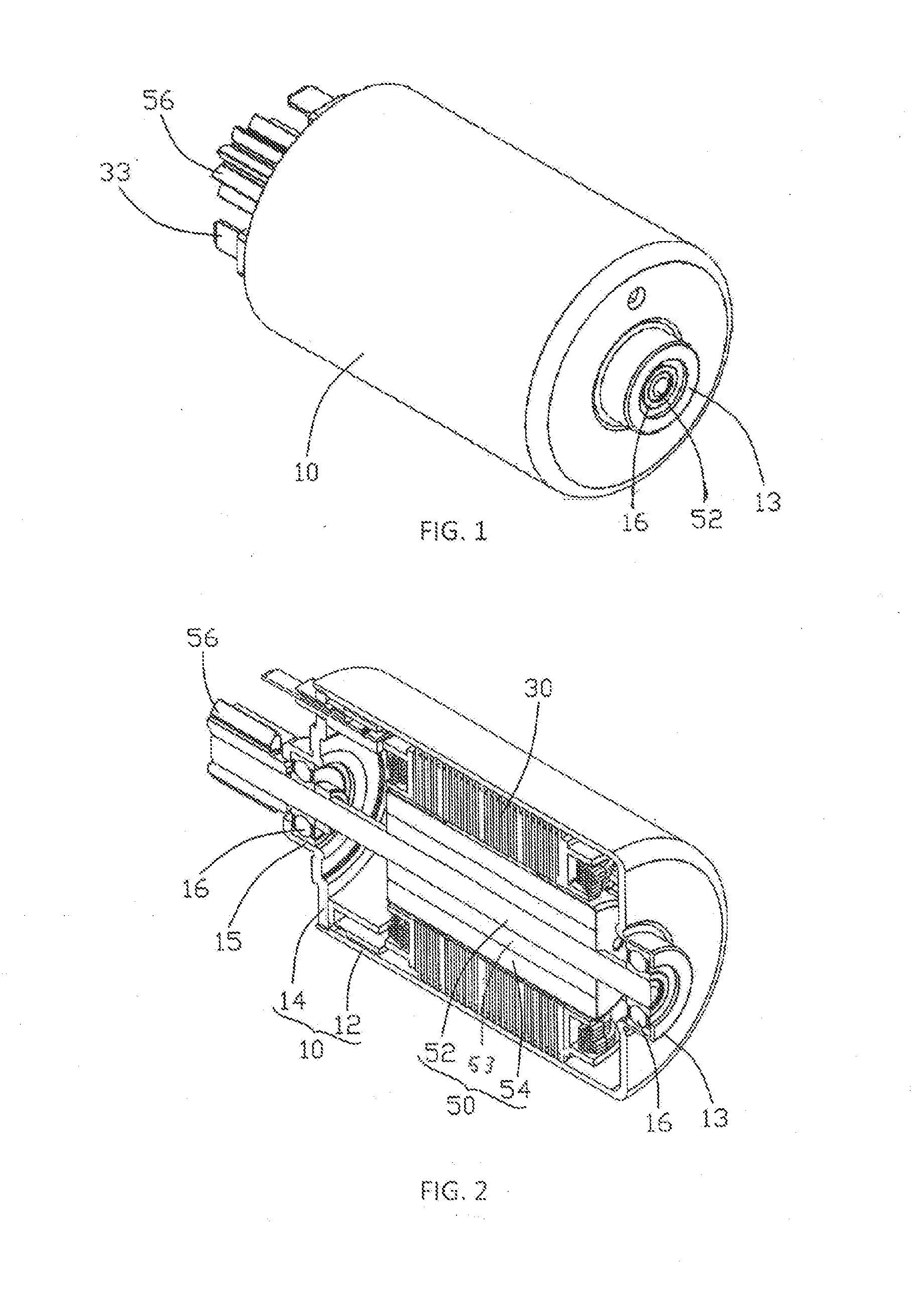
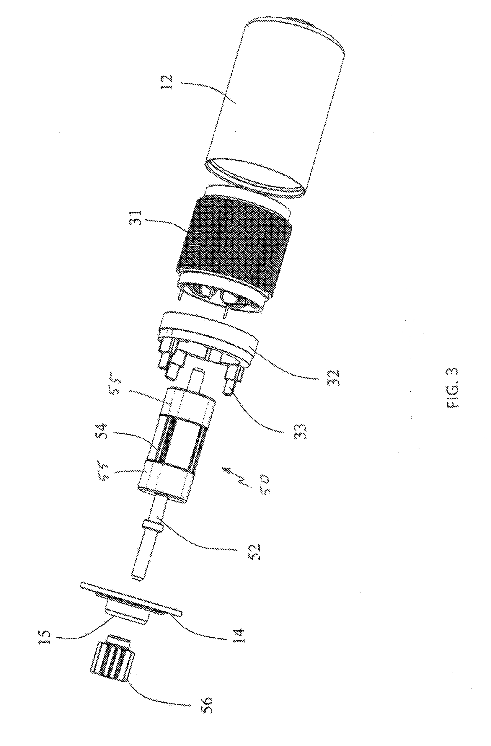
[0032]FIGS. 1 to 8 illustrate an electric motor incorporating a stator structure according to a first exemplary embodiment of the present invention. The illustrated motor is an inner rotor BLDC motor and comprises a stator structure 30 and a rotor 50. The stator structure includes a wound stator 31 fitted to a housing 10. The stator 31 includes a laminated stator core 35 and stator windings 37 wound about teeth of the stator core. The rotor is a permanent magnet rotor, having a shaft 52, a rotor core 53 fixed to the shaft (preferably as a press fit to avoid use of glue) and one or more permanent magnets 54 fitted to the rotor core. In this embodiment, there are four magnets and two rotor caps 55 covering the axial ends of the magnets and the rotor core is a laminated core produced by stacking a plurality of electrical steel laminations to provide a flux path for the magnet field produced by the magnets as well as a means to connected the magnets to the shaft 52. The rotor is rotatab...


PUM


Abstract

An electric motor includes a rotor and a wound stator structure. The stator structure includes a housing, a laminated stator core and windings wound around the stator core. The laminations of the stator core have an annular body and a plurality of teeth extending radially inwardly from the annular body. Projections and recesses are formed at the outer edge of the annular body. When assembled, the recesses of one lamination are aligned with the projections of an adjacent lamination such that when fitting the stator into the housing the projections may be deformed into an axially adjacent recess by contact with the housing. Thus the stator core contacts the housing at discrete locations.

Description

CROSS REFERENCE TO RELATED APPLICATIONS[0001]This non-provisional patent application claims priority under 35 U.S.C. §119(a) from Patent Application No. 201410837269.5 filed in The People's Republic of China on Dec. 26, 2014, the entire contents of which are hereby incorporated by reference.FIELD OF THE INVENTION[0002]This invention relates to an electric motor and in particular, to the structure of a wound stator for an inner rotor motor.BACKGROUND OF THE INVENTION[0003]An electric motor has a movable part referred to as a rotor and a stationary part referred to as a stator. The rotor is connected to a load which is to be moved by the motor. Generally the rotor is arranged to rotate relative to the stator. The rotor and the stator generate an electromagnetic interaction to move the rotor and thus drive the load. According to a position relation between the rotor and the stator, motors are also classified into an inner rotor type and an outer rotor type. As the name implies, in an i...

Claims


Application Information

Patent Timeline
IPC IPC(8): H02K1/18H02K3/34H02K1/16H02K1/27H02K5/22
CPCH02K1/185H02K1/278H02K3/345H02K1/16H02K5/225
Inventor LI, YONG BINJIANG, LONG SHUNFAN, XIAN CHUNWANG, PING
Owner JOHNSON ELECTRIC INTERNATIONAL AG
Why Eureka
Try Eureka