Mounting Frame Comprising a PE Contact

Active Publication Date: 2019-12-19
HARTING ELECTRIC GMBH & CO KG
View PDF0 Cites 0 Cited by
  • Summary
  • Abstract
  • Description
  • Claims
  • Application Information

AI Technical Summary

Benefits of technology

The patent text describes a mounting frame that can be easily inserted into a housing, making fitting easier for production staff. The frames can have cables manufactured before assembly, and the housing is made of metal, which provides stability and can be used for earthing. The technical effects of the patent are improved ease of fitting, enhanced stability, and improved earthing capabilities.

Problems solved by technology

The disadvantage of the prior art is that in the solutions known in the art, the PE contact cannot be used with a plastics mounting frame.

Method used


Image

  • Mounting Frame Comprising a PE Contact
  • Mounting Frame Comprising a PE Contact

Examples


Embodiment Construction

[0030]The figures contain partially simplified, schematic representations. Identical reference numbers are used in part for the same, but possibly not identical, elements. Different views of the same elements could have different scales.

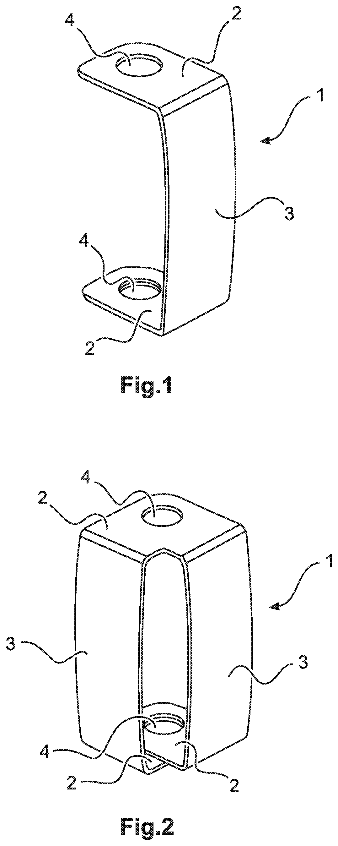
[0031]FIG. 1 shows a perspective representation of an integral PE contact 1. This has the shape of a “u” standing on one of the two limbs 2. The two limbs of the “u” are connected to one another by a connection piece 3. This means that the shape of the PE contact 1 is comparable with a so-called C-carrier. In this set position, the PE contact 1 can be mounted on the mounting frame 5.

[0032]The limbs 2 each have a recess 4. The recess 4 is round in design and is used as a through-hole for the fastening means for mounting the PE contact 1 on the mounting frame 5 or for fastening means for mounting a plug insert.

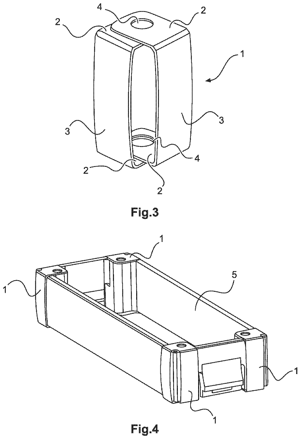
[0033]FIG. 2 shows a perspective representation of an alternative integral, two-limb PE contact 1. The PE contact 1 is formed from one part. If ...


PUM


Abstract

The invention relates to a mounting frame (5) which comprises at least one PE contact (1) and can be inserted into the housing from a plug-in end and / or from a terminal end. The at least one PE contact (1) is arranged on the mounting frame (5). Previously known PE contacts can be contacted only from one end, whereas the disclosed PE contact (1) can be contacted from the terminal end and / or the plug-in end.

Description

TECHNICAL FIELD[0001]The disclosure relates to a mounting frame comprising a PE contact. Contacts of this kind are needed in order to guarantee the earthing of a plug connector with contacts inserted.BACKGROUND[0002]DE 10 2014 109 351 B3 discloses a plug connector with a protective conductor bridge. The protective conductor bridge serves as a connection between two PE contacts in a plastic housing. It has to be mounted on the side of the plug insert.[0003]DE 100 09 749 B4 discloses a contact fastening for rectangular plug connectors in which a means for bringing a PE contact into contact is also disclosed. In this case, the PE contact is engaged in its own chamber and aligned with a flange opening and a spring element.[0004]DE 10 2013 113 976 B4 discloses a mounting frame with a connection region for a PE contact. The metallic design of the mounting frame means that earthing is guaranteed within a metallic housing.[0005]The disadvantage of the prior art is that in the solutions know...

Claims


Application Information

Patent Timeline
IPC IPC(8): H01R13/648H01R13/518
CPCH01R13/518H01R13/648H01R13/652H01R13/6582
Inventor BEISCHER, THOMASSCHENK, FLORIAN
Owner HARTING ELECTRIC GMBH & CO KG
Why Eureka
Try Eureka