
Stirring device for treatment of photoresist settlement and photoresist tank

a technology of stirring device and photoresist tank, which is applied in the direction of mixer, mixer accessories, mixing, etc., can solve the problems of affecting the quality of products, affecting the use effect, and the design of the photoresist tank cannot prevent or treat the photoresist settlement, etc., to achieve convenient and efficient use, high safety, and rapid stirring speed

Active Publication Date: 2019-12-26
WUHAN CHINA STAR OPTOELECTRONICS TECH CO LTD
View PDF32 Cites 5 Cited by
  • Summary
  • Abstract
  • Description
  • Claims
  • Application Information

AI Technical Summary

Benefits of technology

The present disclosure provides a stirring device for treatment of photoresist settlement. This device uses an inner telescopic shaft to unfold the stirring component. The rotary rod drives the sleeve shaft to rotate, which causes the stirring component to rotate. The stirring is performed gradually from a bottom portion of the device to the top, which results in more uniform stirring of the photoresist. This device is easy to use, saves considerable resources, and is fast and safe.

Problems solved by technology

Since the CF adopts the negative photoresist (i.e., a part of exposed photoresist will be retained), if the homogeneity of the photoresist is not good, after the procedures of vacuum pumping and preheating, the amounts of retained photoresist may be different due to the volatilization of a solvent in the photoresist, which results in a difference in characteristic values, thereby influencing the quality of the products.
An existing photoresist tank has no design for preventing or treating the photoresist settlement.
Since the photoresist tank is heavy, the operation is inconvenient.
Moreover, since the photoresist is inflammable and possesses some toxicity, there also exists a safety problem in the operation.

Method used


Image

  • Stirring device for treatment of photoresist settlement and photoresist tank
  • Stirring device for treatment of photoresist settlement and photoresist tank
  • Stirring device for treatment of photoresist settlement and photoresist tank

Examples


Embodiment Construction

[0027]In the following, the present disclosure will be further illustrated in combination with the drawings.

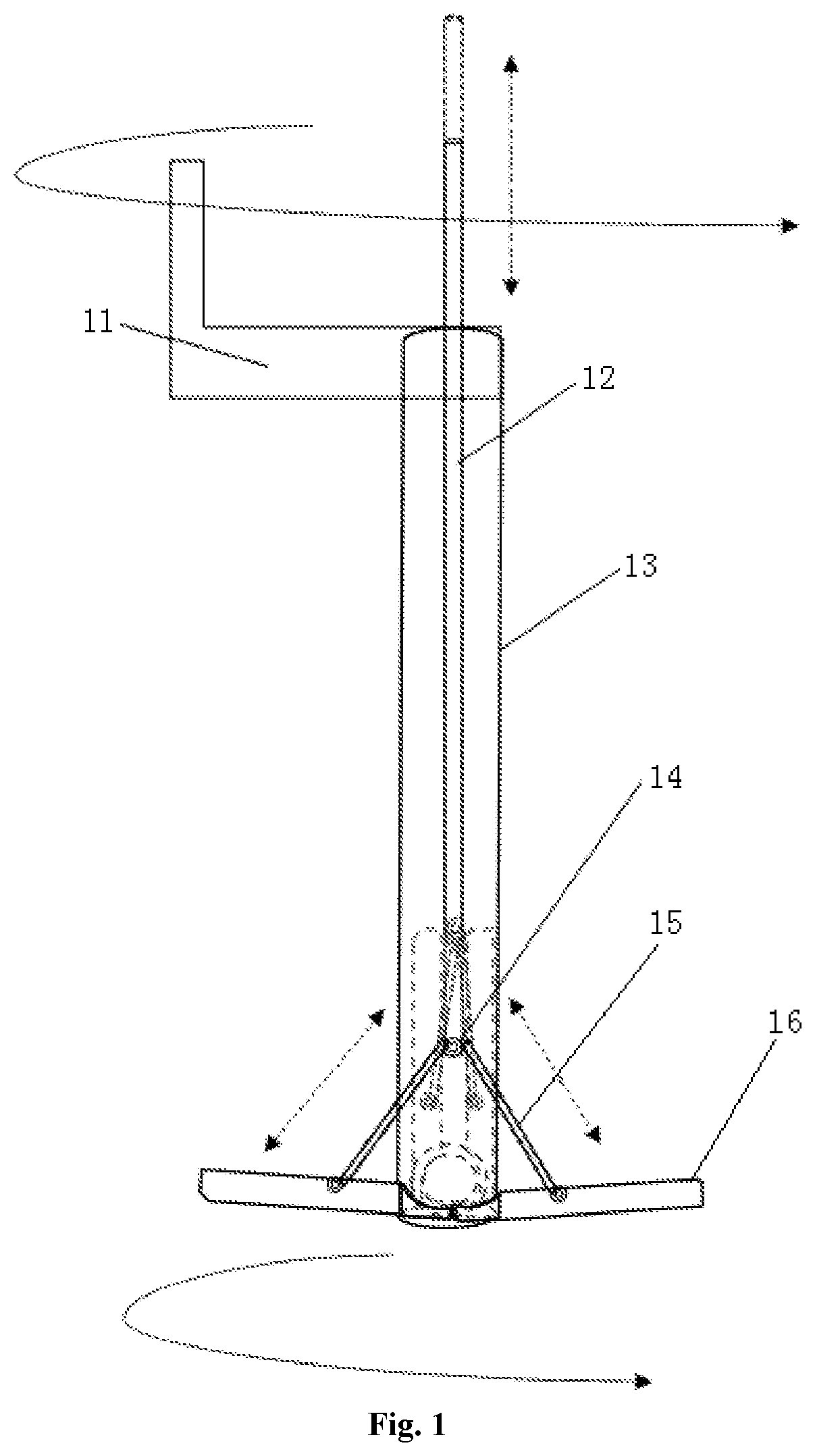
[0028]FIG. 1 schematically shows a stirring device for treatment of photoresist settlement, comprising:

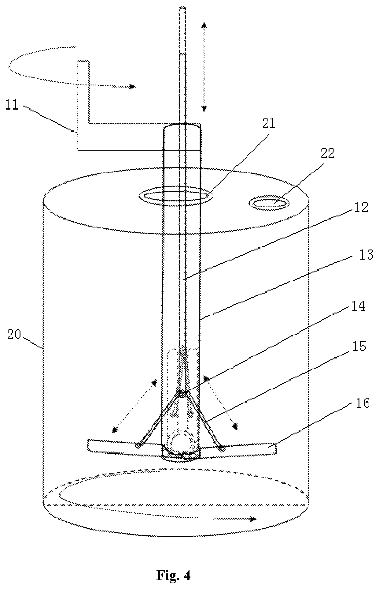
[0029]a sleeve shaft 13, an inner telescopic shaft 12, a stirring component, and a rotary rod 11,

[0030]wherein the rotary rod 11 is mounted on an upper end of the sleeve shaft 13 for driving the sleeve shaft 13 to rotate; the stirring component is mounted on a lower end of the sleeve shaft 13 and rotates with the sleeve shaft 13; and the inner telescopic shaft 12 is arranged inside of the sleeve shaft 13 and connected to the stirring component for controlling opening and closing of the stirring component. The stirring device brings about excellent stirring effects, has a simple structure, enables convenient and efficient operations, and improves the safety performance.

[0031]As shown in FIG. 1, in one preferred embodiment, the sleeve shaft 13 is in a cask shape, which is conve...


PUM


Abstract

Involved is the technical field of a stirring device, specifically a stirring device for treatment of photoresist settlement and a photoresist tank. The stirring device includes a sleeve shaft, an inner telescopic shaft, a stirring component, and a rotary rod, wherein, the rotary rod is mounted on an upper end of the sleeve shaft for driving the sleeve shaft to rotate; the stirring component is arranged on a lower end of the sleeve shaft and rotates with the sleeve shaft; and the inner telescopic shaft is arranged inside of the sleeve shaft and connected to the stirring component for controlling opening and closing of the stirring component. Stirring plates approach a bottom portion of the photoresist tank, at which moment manual control is adopted to control stirring of the stirring device upward from the bottom gradually, so as to achieve the objective of homogeneous component of the photoresist. The photoresist is stirred to be more homogeneous. A lot of manpower and material resources are saved. The stirring device enables high stirring speed and high safeness.

Description

CROSS-REFERENCE TO RELATED APPLICATIONS[0001]This application claims the priority of Chinese patent application CN 201710181986.0, entitled “Stirring device for treatment of photoresist settlement and photoresist tank” and filed on Mar. 24, 2017, the entirety of which is incorporated herein by reference.FIELD OF THE INVENTION[0002]The present disclosure relates to the technical field of a stirring device, and in particular, to a stirring device for treatment of photoresist settlement and a photoresist tank.BACKGROUND OF THE INVENTION[0003]In the manufacture of TFT-LCDs (liquid crystal display devices), a photoresist is required, wherein in the manufacture of a CF (color filter) substrate, necessary RGB photoresist has a strict requirement for the homogeneity of a photoresist amount. The long-distance transportation and the long-period storage of the photoresist may result in the settlement thereof. In a photoresist tank, the amount of photoresist in an upper part is smaller than tha...

Claims


Application Information

Patent Timeline
Patent Type & Authority Applications(United States)
IPC IPC(8): B01F7/00B01F7/18B01F15/00
CPCB01F7/00058B01F7/0095B01F7/00716B01F7/18B01F15/00506B01F27/2124B01F27/2312B01F27/90B01F35/3202B01F27/0541B01F35/22161B01F35/3204
Inventor TANG, NINGLIN
Owner WUHAN CHINA STAR OPTOELECTRONICS TECH CO LTD
Learn More