Humidification device, humidifier and ventilator

a technology of humidifier and ventilator, which is applied in the direction of respirator, medical devices, other medical devices, etc., can solve the problem and achieve the effect of relatively low heat exchange efficiency of ventilator

Active Publication Date: 2018-01-25
BMC MEDICAL
View PDF4 Cites 2 Cited by
  • Summary
  • Abstract
  • Description
  • Claims
  • Application Information

AI Technical Summary

Benefits of technology

[0017]Compared with the prior art, according to the embodiments of the present disclosure, by providing the reserved interval between the outlet of the liquid inlet pipeline and the bottom of the heating area, the liquid level of the liquid in the heating area does not exceed the outlet of the liquid inlet pipeline, so that the phenomenon of low heating efficiency caused by more water in the heating area can be avoided. Furthermore, the humidification device can implement dynamic water supplementation, so that a constant amount of liquid in the heating area can be ensured, thereby avoiding dry burning.
[0018]According to the embodiments of the present disclosure, a liquid supplementing operation fir the humidification device may be implemented by replacement or by supplementing liquid to the liquid storage area, so that the humidifier is prevented from being frequently opened or closed in a liquid adding process, and thus the humidifier is used very conveniently and efficiently. Furthermore, the heating element is not exposed in a liquid adding process, so that danger of a patient being scalded may be avoided.

Problems solved by technology

A technical problem to be solved by the present disclosure is to overcome deficiencies in the prior art such as the heating efficiency of a ventilator being relatively low when the amount of water in a humidification device is adequate.

Method used


Image

  • Humidification device, humidifier and ventilator
  • Humidification device, humidifier and ventilator
  • Humidification device, humidifier and ventilator

Examples


second embodiment

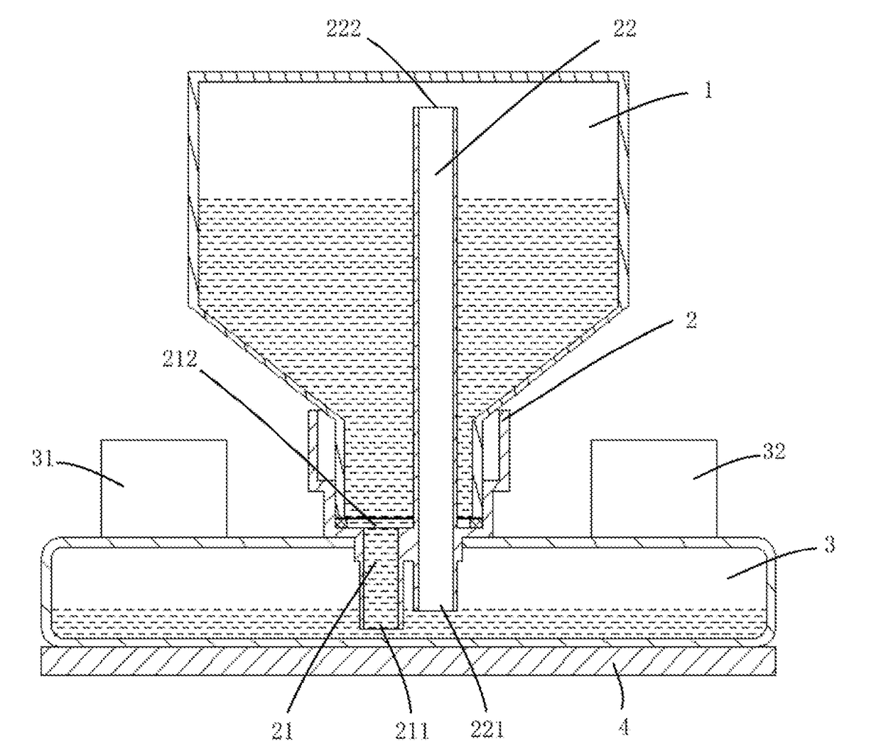
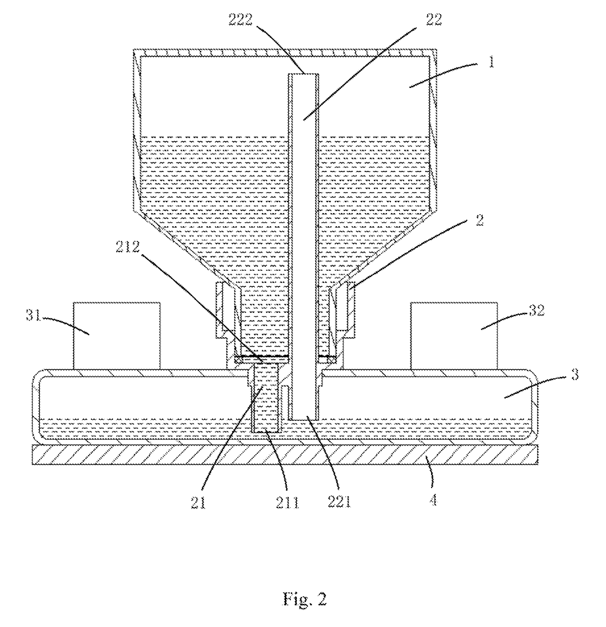
[0036]FIG. 2 illustrates the humidification device according to the present disclosure. As shown in FIG. 2, the liquid conveying device 2 comprises the liquid inlet pipeline 21 and the air outlet pipeline 22. The liquid inlet pipeline 21 is configured to convey the liquid in the liquid storage area 1 to the heating area 3, and the air outlet pipeline 22 is configured to convey the air in the heating area 3 to the liquid storage area 1. Both an outlet 211 of the liquid inlet pipeline 21 and an inlet 221 of the air outlet pipeline 22 extend into the heating area 3, the inlet 212 of the liquid inlet pipeline 21 is lower than the outlet 222 of the air outlet pipeline 22, the outlet 211 of the liquid inlet pipeline 21 is lower than the inlet 221 of the air outlet pipeline and is closer to a bottom of the heating area 3 than the inlet 221 of the air outlet pipeline. The air outlet pipeline 22 may be straight or may be bent.

[0037]When the embodiment as shown in FIG. 2 is applied and when t...

third embodiment

[0040]FIG. 3 illustrates the humidification device according to the present disclosure. In the embodiment as shown in FIG. 3, a suspension seal element 5, which may block off the outlet 20, positioned in the heating area 3, of the liquid inlet pipeline 21 in the liquid conveying device 2, is arranged in the heating area 3. A density of the suspension seal element 5 is smaller than that of the liquid, and is arranged directly facing the outlet 20 of the liquid inlet pipeline 21.

[0041]When there is no liquid in the heating area 3, the suspension seal element 5 contacts the bottom surface of the heating area 3, and is separated from the outlet 20 of the liquid inlet pipeline 21. Consequently, the liquid in the liquid storage area 1 may flow into the heating area 3 via the liquid inlet pipeline 21. As the water continuously enters the heating area 3, the suspension seal element 5 whose density is lower than that of the water liquid gradually rises as the liquid level rises until the out...

fourth embodiment

[0045]FIG. 4 illustrates the humidification device the present disclosure.

[0046]As shown in FIG. 4, in the humidification device according to the embodiment of the present disclosure, the heating area 3 is provided with an elastic sealing element 6, which may block off the outlet 29 of the liquid inlet pipeline 21, under the outlet 22 of the liquid inlet pipeline 21 of the liquid conveying device 2. The elastic sealing element 6 comprises a sealing plate 61 and an elastic element 62 arranged at a bottom of the sealing plate. The sealing plate 61 faces towards the outlet 29 of the liquid inlet pipeline 21, and the elastic element 62 props against between the bottom of the sealing plate 61 and the bottom of the heating area 3. The sealing plate 61 is provided with a sealing member 610, and the external shape of the sealing member 610 fits to the internal shape of the outlet 20 of the liquid inlet pipeline 21, so that the sealing member 610 can block off the outlet 20 of the liquid in...


PUM


Abstract

The present disclosure discloses a humidification device, and a humidifier and a ventilator to overcome deficiencies in the prior art such as the healing efficiency of a ventilator being relatively low when the amount of water in a humidification device is adequate. The humidification device comprises a heating area and a liquid conveying device conveying n liquid to the heating area, the liquid conveying device comprising a liquid inlet pipeline, the liquid inlet pipeline extending into the heating area and extending to a bottom of the heating area, and a reserved interval being provided between an outlet of the liquid inlet pipeline and the bottom of the heating area. According to the embodiments of the present disclosure, it is ensured that the heating efficiency may be increased and the heating time may be reduced in the case of continuous use.

Description

CROSS-REFERENCES TO RELATED APPLICATION[0001]This application is the national phase entry of International Application No. PCT / CN2015 / 100055, filed on Dec. 31, 2015, which is based upon and claims priority to Chinese Patent Application No. CN201510012049.3, filed on Jan. 9, 2015, the entire contents of which are incorporated herein by reference.TECHNICAL FIELD[0002]The present disclosure relates to human respiratory regulation technologies, and more particularly, to a humidification device, a humidifier and a ventilator.BACKGROUND OF THE INVENTION[0003]A humidifier of a ventilator is mainly used for increasing humidity of air conveyed to a patient. The air, for a medical purpose, generally does not contain adequate moisture. If the air is used directly, it may damage or irritate a respiratory tract or an upper respiratory tract of a user. Also, the respiratory tract or the upper respiratory tract of the user may be affected by dry and dense secreta of a bypass patient, which may cau...

Claims


Application Information

Patent Timeline
Patent Type & Authority Applications(United States)
IPC IPC(8): A61M16/16A61M16/10
CPCA61M16/162A61M16/109A61M16/00A61M2205/3653A61M16/167
Inventor LIU, LIJUNZHI, JIANXINZHUANG, ZHI
Owner BMC MEDICAL
Why Eureka
Try Eureka