Method and device for maintaining a nozzle print head

a technology of print head and nozzle, applied in the field of print head, can solve the problems of loss of time, removal or opening of the cover of the print head, dirt (or ink projection) inside the cavity,

Active Publication Date: 2019-12-26
DOVER EURO SARL
View PDF0 Cites 5 Cited by
  • Summary
  • Abstract
  • Description
  • Claims
  • Application Information

AI Technical Summary

Benefits of technology

[0024]For example said actuator or means make it possible to drive said spraying nozzle in rotation over an angle at least equal to 60° or 90° or 180°.
[0027]Thus, the latter being integrated into the print head, the risk of a flow or of a leak of cleaning fluid in the direction of the means for driving is reduced or prevented.
[0033]According to a particular embodiment, a print head according to the invention can comprise an accelerometer, which will make it possible to provide information concerning the orientation of the print head. This accelerometer is for example arranged inside the cavity for the circulation of jets or inside a dedicated cavity with one or several electronic components, which can be located in the vicinity of the cavity for the circulation of jets.
[0037]Preferably, at least one spraying nozzle makes it possible to project a cleaning fluid in the form of a jet that diverges with an angle between 1° and 20° along an axis parallel to a flow direction of the ink jets.

Problems solved by technology

A 1st problem linked to this type of print head is the deposition of dirt (or projections of ink) inside the cavity, in particular on the electrode or electrodes or on the walls or in the gutter for recovering drops not used for printing.
However, the cover of the print head has to be removed or opened.
It is desirable to avoid manual intervention from the operator on the one hand because, in particular, such an intervention is a loss of time and that dirt is possible during this operation, but also, on the other hand, because the impact of this intervention on the effectiveness of the print head is not controlled (there can in particular be a disturbance effect on later operation).
Another problem is that of the forming of a jet, for example a jet of solvent, for the cleaning of the ink circuit; this jet is projected, by the nozzles that are usually used to form the ink jets, outside of the cavity which can be dirty and expensive (the liquid projected is indeed then not recoverable).
The same problems arise for a print head of the CIJ type.

Method used


Image

  • Method and device for maintaining a nozzle print head
  • Method and device for maintaining a nozzle print head
  • Method and device for maintaining a nozzle print head

Examples


Embodiment Construction

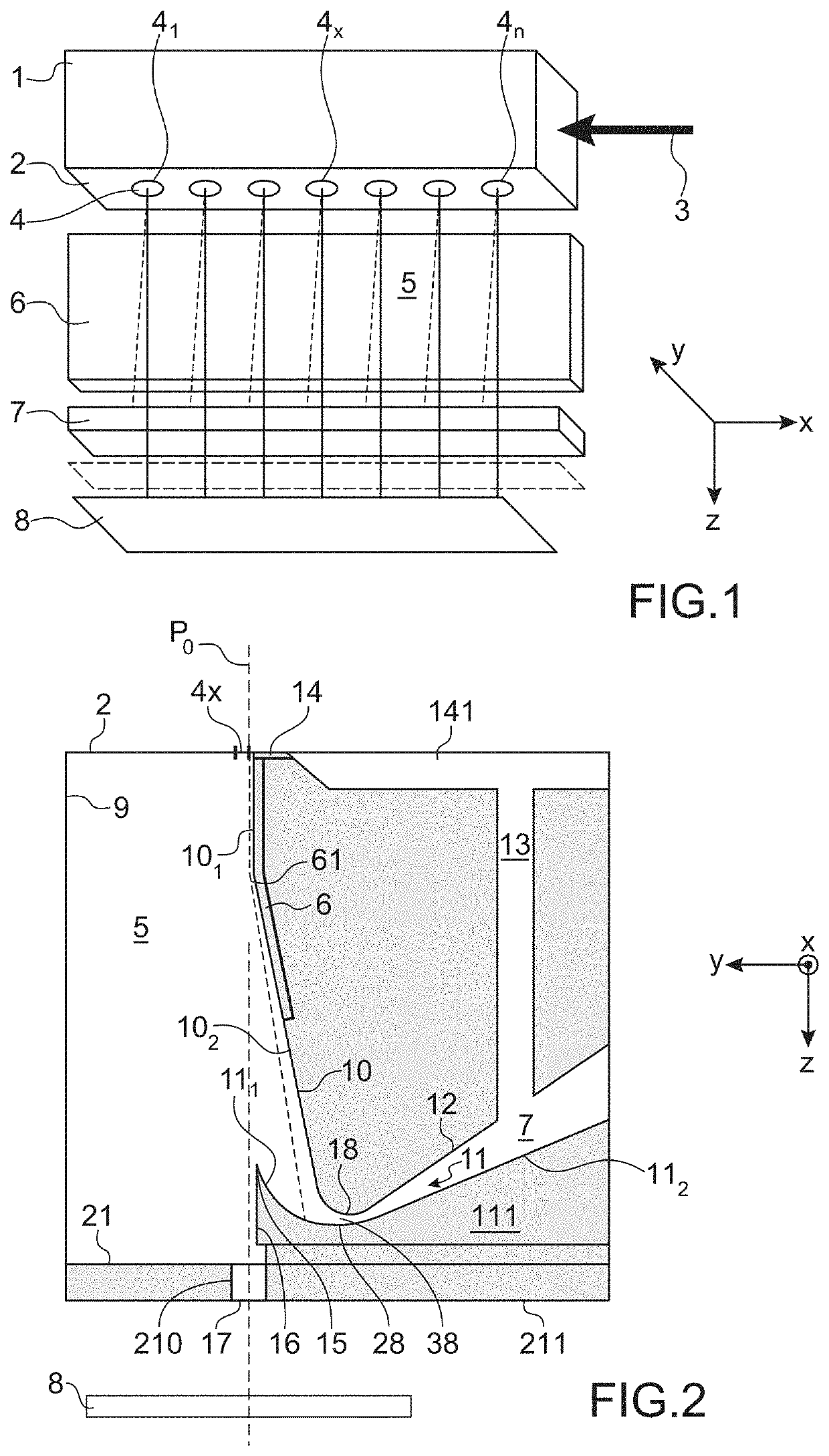
[0094]A structure of a print head to which the invention can be applied is explained hereinbelow, in liaison with FIG. 1.

[0095]The head comprises a drop generator 1. This generator comprises a nozzle plate 2 on which are aligned, along an axis X (contained in the plane of the figure), a whole number n of nozzles 4, of which a first 41 and a last nozzle 4n.

[0096]The first and last nozzles (41, 4n) are the nozzles that are the farthest apart from each other.

[0097]Each nozzle has an axis of emission of a jet parallel to a direction or an axis Z (located in the plane of FIG. 1), perpendicular to the nozzle plate and to the axis X mentioned hereinabove. A third axis, Y, is perpendicular to each one of the two axes X and Z, the two axes X and Z extending in the plane of FIG. 1.

[0098]In the figure, the nozzle 4x is shown. Each nozzle is in hydraulic communication with a pressurised stimulation chamber. The drop generator comprises as many stimulation chambers as there are nozzles. Each cha...


PUM


Abstract

A print head of a continuous ink jet printer comprising: a cavity for the circulation of jets, delimited laterally by a 1st side wall and a 2nd side wall, both at least partially parallel to a direction of flow of the jets in the cavity, at least one nozzle for producing at least one ink jet in the cavity, at least one electrode for sorting drops or segments of one or several of the jets intended for printing from drops or segments that are not used for printing; an outlet slot, open onto the exterior of the cavity and allowing the exiting of the drops or segment of ink intended for printing, at least one gutter for recovering drops or segments not intended for printing, at least one spraying nozzle, arranged in the cavity, for projecting at least one cleaning fluid towards at least one inner portion of the cavity and a motor driving the at least one spraying nozzle in rotation about an axis (x), for example perpendicular to a direction of flow of the jets in the cavity; a supply circuit supplying at least the spraying nozzle with cleaning fluid.

Description

CROSS-REFERENCE TO RELATED APPLICATIONS[0001]This application claims priority from French Patent Application No. 1855502, filed Jun. 21, 2018. The content of this application is incorporated herein by reference in its entirety.TECHNICAL FIELD AND PRIOR ART[0002]The invention relates to the print heads of printers or continuous ink jet printers, in particular, binary continuous ink jet printers provided with a multi-nozzle drop generator or with a multi-jet generator.[0003]Continuous ink jet printers comprise a print head, which comprises a generator of drops of ink associated with a cavity for forming jets which contains means, most often one or several electrodes, in order to separate the trajectories of drops produced by the generator and direct them to a printing support or towards a gutter for recovering.[0004]A 1st problem linked to this type of print head is the deposition of dirt (or projections of ink) inside the cavity, in particular on the electrode or electrodes or on the...

Claims


Application Information

Patent Timeline
Patent Type & Authority Applications(United States)
IPC IPC(8): B41J2/165B41J2/02
CPCB41J2/02B41J2/16552B41J2/14B41J2/185B41J2002/1853B41J2/08B41J2/105B41J2/1707
Inventor BONNETON, DAMIENGOBIN, CAMILLEABADIE, JEAN-FRANÇOISROLLAND, JEAN-MARIEHUGI, NIKLAUS
Owner DOVER EURO SARL
Why Eureka
Try Eureka