
Image forming apparatus

a technology of image forming apparatus and forming plate, which is applied in the direction of electrographic process apparatus, instruments, optics, etc., can solve the problems of inability to identify type, difficulty in correct designation of sheet type, and considerable amount of time, so as to achieve the effect of rapid start-up

Active Publication Date: 2020-01-30
KONICA MINOLTA INC
View PDF0 Cites 3 Cited by
  • Summary
  • Abstract
  • Description
  • Claims
  • Application Information

AI Technical Summary

Benefits of technology

The invention aims to enable quick startup and smooth transition to a rotation state by identifying the type of sheet used and adjusting the speed accordingly. This results in a faster and more efficient operation of the motor.

Problems solved by technology

However, in recent years, a wide variety of types of sheets can be used in image forming apparatuses, making it difficult for the user to correctly designate the type of sheets.
However, the type cannot be identify before the start of the conveyance of the sheet.
Such a large moment of inertia contributes to stable rotation but results in a considerable amount of time required for starting up the polygon mirror in a stopped state to be in a stable rotation state, in which image forming can be performed.
A sequence of determining the type and then setting the target speed to start up the polygon mirror leads to a delay in the start of the pattern exposure, resulting in a longer FPOT, in the image forming apparatus having, the sensor for identifying the type provided on the conveyance path as described above.
However, if the type identified does not match the provisional type, the rotation speed of the polygon mirror needs to be changed from the provisional target speed to the target speed corresponding to the type identified, in such a case, this change in the rotation speed requires a considerable amount of time due to the inertia acting to maintain the stable rotation state with the provisional target speed.
All things considered, the technique disclosed in JP 2016-99599 A cannot be applied to the image forming apparatuses involving the identification of the type, and thus cannot solve the problem described above.

Method used


Image

  • Image forming apparatus
  • Image forming apparatus
  • Image forming apparatus

Examples


Embodiment Construction

[0038]Hereinafter, one or more embodiments of the present invention will be described with reference to the drawings. However, the scope of the invention is not limited to the disclosed embodiments.

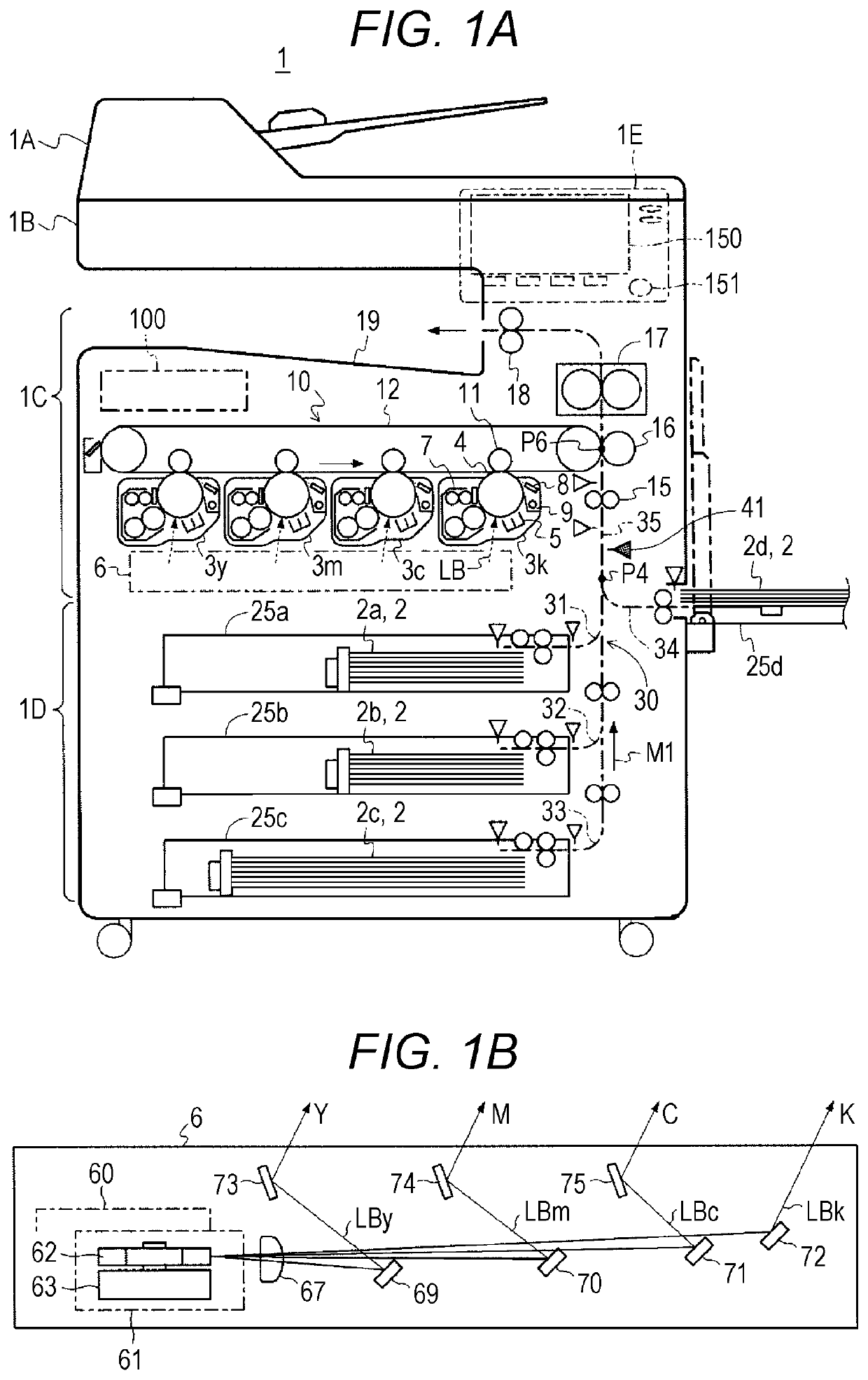
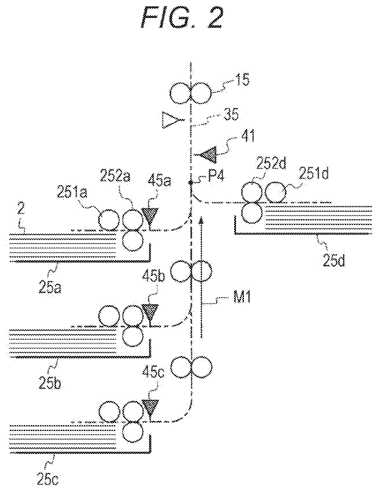
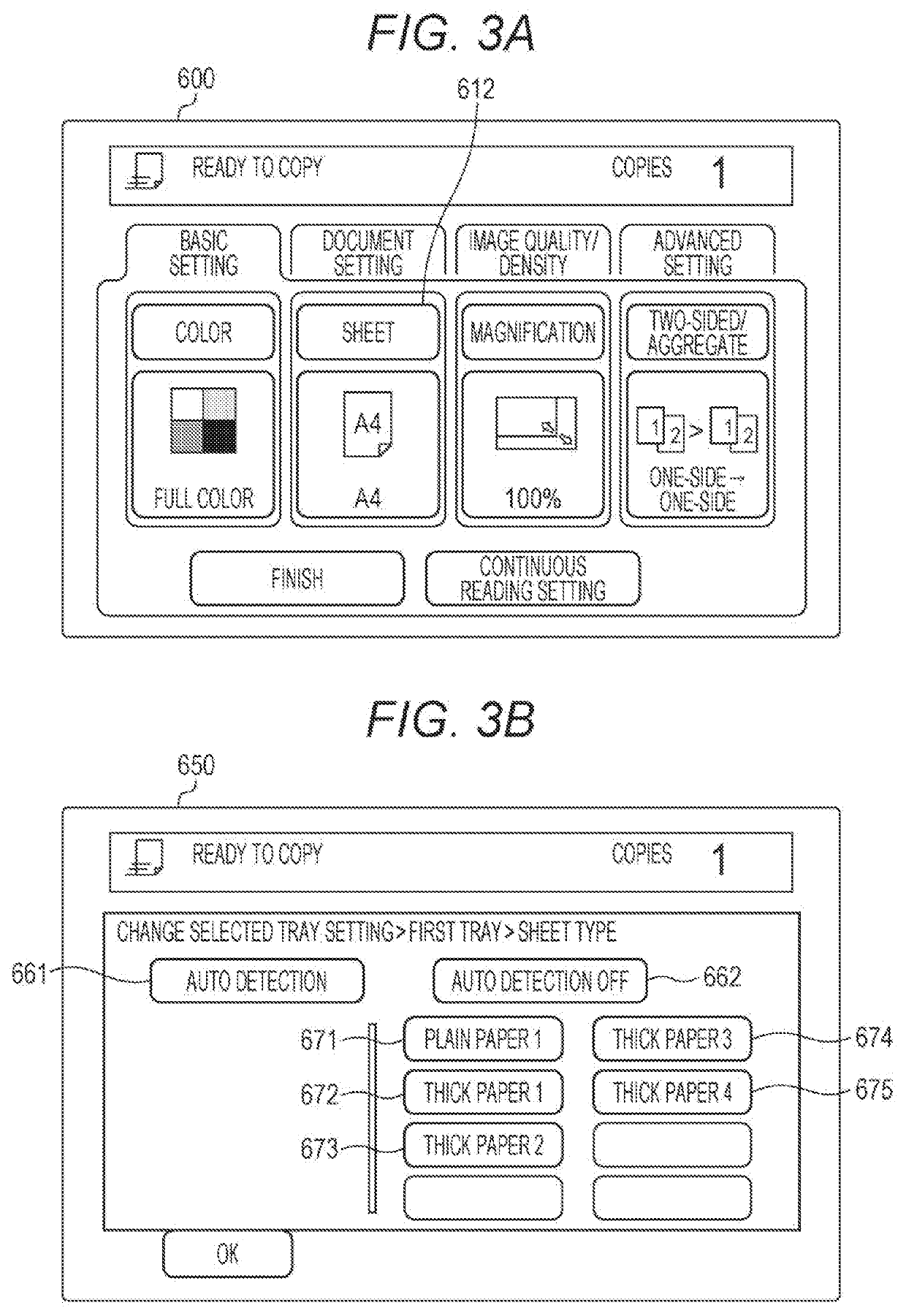
[0039]FIGS. 1A and 1B illustrate an overview of a configuration of an image forming apparatus 1 according to an embodiment of the present invention. FIG. 2 illustrates an example of an arrangement of sheet feed sensors 45. FIGS. 3A and 3B illustrate examples of respective operation screens 600 and 650 related to identification of a type SK of a sheet 2.

[0040]The image forming apparatus 1 in FIG. 1A is a multi-functional peripheral (MFP) integrally having functions of a copier, a printer, a facsimile machine, an image reader, and the like.

[0041]The image forming apparatus 1 includes an auto document feeder (ADF) 1A, a flatbed scanner 1B, an electrophotographic color printer 1C, a sheet cabinet 1D, an operation panel 1E, and the like.

[0042]The sheet cabinet 1D is of a three-stage draw out t...


PUM


Abstract

An image forming apparatus that conveys a sheet and prints an image on the sheet, includes: a sheet feed tray on which the sheet is placed; a motor that drivingly rotates a polygon mirror with which a latent image corresponding to the image is formed; a hardware processor that identifies a type of the sheet based on an output from a sensor provided between the sheet feed tray and a position at which the printing takes place, on a conveyance path for the sheet; and a motor controller that changes a rotation speed of the motor to a first speed, starting from a startup timing synchronized with starting of conveyance of the sheet, wherein the startup timing is set in such a manner that an identification tinting at which the type of the sheet is identified arrives while the changing to the first speed is still in progress.

Description

[0001]The entire disclosure of Japanese patent Application No. 2018-139397, filed on Jul. 25, 2018, is incorporated herein by reference in its entirety.BACKGROUNDTechnological Field[0002]The present invention relates to an image forming apparatus.Description of the Related Art[0003]Image forming apparatuses, such as a printer, a copier, or a multi-functional peripheral (MFP), include a sheet feed tray (a tray for sheets to be fed) in which a plurality of sheets, each used as an image recording medium, are set. Printing is performed with the sheet conveyed from the sheet feed tray to a print position inside the apparatus.[0004]A known function of this type of image forming apparatus includes a function of ting an operation condition so that an appropriate image can be obtained based on the type of the sheet. For example, in an electrophotographic image forming apparatus, it is a common practice that sheets are classified according to their basis weight, and conveyance speed, developi...

Claims


Application Information

Patent Timeline
Patent Type & Authority Applications(United States)
IPC IPC(8): G03G15/00
CPCG03G15/043G03G15/5029G03G15/6529
Inventor SUGAI, SHUN
Owner KONICA MINOLTA INC
Learn More