Method for boring bottle-like holes having a defined geometry by means of pulsed laser radiation

a laser radiation and hole technology, applied in the direction of laser beam welding apparatus, fuel injection apparatus, mechanical apparatus, etc., can solve the problems of increasing labor costs, inability to create fluidically optimal conditions, and significant negative effects on nozzle stability and thus on functional reliability and durability

Inactive Publication Date: 2012-08-07
PRELATEC
View PDF32 Cites 10 Cited by
  • Summary
  • Abstract
  • Description
  • Claims
  • Application Information

AI Technical Summary

Benefits of technology

[0031]1. The intensity profile or, respectively, the K number of the laser radiation is changed, to with either internally, i.e. in the laser resonator itself, by means of suitable measures such as chronological variation of the pumping process or by changing the optical resonator configuration, or externally, i.e. outside of the laser resonator, e.g. by installing suitable optical elements such as diffractive optics into the beam. Since in general an extremely reliable functioning of the laser itself is strived for and interventions in the laser function, especially in industrial continuous operation, harbor the danger of instabilities, the external methods of beam profile alterations are of particular practical interest. For example, during the transition from the pre-boring segment to the shape boring segment, a diffractive optical structural element can be installed swiftly, i.e. practically without any loss of time, in the beam path that gives the laser beam the desired shape. Another advantage of this is the fact that drastic changes are possible without any problem that would not be realizable to this extent by means of interventions in the laser function.
[0040]f) Analogous results can be achieved through a variation of the laser beam diameter on the focusing lens during the boring process. Such a change of the diameter can be realized, for example, by means of suitable fast adaptive optics. Since the focus diameter depends reversely proportionately on the bundle diameter on the lens, the focus diameter as well as the form of the caustics are altered in this manner. During this process, one could for example start the boring process with a relatively small beam diameter and consequently with a relatively large focus diameter. Analogously to point a), the sharpness of the focusing is then improved by means of enlarging the beam diameter, thereby also protecting the fluid exit edge created during the pre-boring phase from any damaging fusion.
[0041]c) Another possibility for the use of fast adaptive optics consists in changing the divergence of the beam bundle impacting on the focusing element during the boring process. This achieves the fact that the focus position is varied in such a magnitude that the bore hole shape is influenced in the desired manner.

Problems solved by technology

But this way it is not possible to create fluidically optimal conditions for the atomization of fluids.
In the case of such large numbers of holes, a considerable negative effect on nozzle stability and thus on functional reliability and durability must be expected in addition to increased labor costs.
What is not appreciated by the prior art is that all the proposals enumerated above lack a deliberate consideration of the characteristics of the interaction between laser radiation and material that are coupled with the wave properties of laser radiation, in particular diffraction, in order to achieve fluidically optimal hole shapes.

Method used


Image

  • Method for boring bottle-like holes having a defined geometry by means of pulsed laser radiation
  • Method for boring bottle-like holes having a defined geometry by means of pulsed laser radiation
  • Method for boring bottle-like holes having a defined geometry by means of pulsed laser radiation

Examples


Embodiment Construction

[0063]Reference will now be made in detail to several embodiments of the invention that are illustrated in the accompanying drawings. Wherever possible, same or similar reference numerals are used in the drawings and the description to refer to the same or like parts or steps. The drawings are in simplified form and are not to precise scale. For purposes of convenience and clarity only, directional terms, such as top, bottom, up, down, over, above, and below may be used with respect to the drawings. These and similar directional terms should not be construed to limit the scope of the invention in any manner. The words “connect,”“couple,” and similar terms with their inflectional morphemes do not necessarily denote direct and immediate connections, but also include connections through mediate elements or devices.

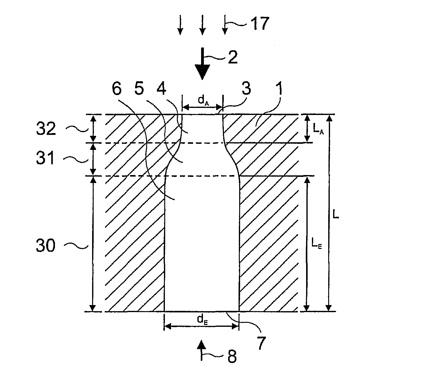
[0064]FIG. 1 shows the cross section of the nozzle hole in accordance with the invention in a first embodiment which simultaneously reflects the basic shape, namely a “bottle...


PUM

PropertyMeasurementUnit
dAaaaaaaaaaa
wave lengthaaaaaaaaaa

Abstract

The present invention is a method and system for the drilling of holes in a workpiece within a diameter range of 20 μm to 500 μm by means of laser radiation. The invention utilizes the beam quality of a laser beam as well as: the polarization of the laser radiation; the parameters of the impulses of the laser used; and, the type and pressure of the process gas used. The method and system utilize means for focusing laser radiation, in particular the ratio of the beam diameter at the site of the focusing element and its focal distance, and wherein the focusing is done in coordination with the beam quality number and wave length and other factors. A first working gas supports the formation of the hole shape and accelerates the drilling process; and, a second working gas is utilized to improve the surface quality of the drilling walls.

Description

CROSS REFERENCE TO RELATED APPLICATIONS[0001]This application is a National Phase Entry of PCT Patent Application Serial No. PCT / EP2008 / 008899, filed Oct. 22, 2008, and claims priority from German Patent Application Serial No. 10 2007 051 408.7, filed Oct. 25, 2007, the entire contents of each of which is herein incorporated fully by reference.FIGURE FOR PUBLICATION[0002]FIG. 1BACKGROUND OF THE INVENTION[0003]1. Field of the Invention[0004]The present invention relates to a method and system for the drilling of holes, of defined geometries. More specifically, the present invention relates to a method and system for the drilling of holes, of defined cross sections of holes, by means of complex laser technologies as further described herein.[0005]2. Description of the Related Art[0006]The related art involves In addition to present conditions on the part of the engine such as combustion chamber shape, air movement and nozzle location, the combustion process in diesel and gasoline engi...

Claims


Application Information

Patent Timeline
Patent Type & Authority Patents(United States)
IPC IPC(8): B23K26/00
CPCB23K26/0054B23K26/0626B23K26/383B23K26/388F02M61/168F02M61/1806F02M61/1846B23K2201/006B23K26/384B23K26/389B23K26/50B23K2101/006
Inventor WALTER, HERBERTSTAUPENDAHL, GISBERT
Owner PRELATEC
Why Eureka
Try Eureka