
Vacuum condition controlling apparatus, system and method for specimen observation

a condition control and vacuum technology, applied in the field of scanning electron microscopes, can solve the problems of difficult observation, many objects that are difficult to observe with conventional sem, and no longer applicable light diffraction,

Active Publication Date: 2020-01-30
FOCUS E BEAM TECH BEIJING CO LTD
View PDF0 Cites 5 Cited by
  • Summary
  • Abstract
  • Description
  • Claims
  • Application Information

AI Technical Summary

Benefits of technology

The patent text describes a vacuum condition controlling apparatus for creating a desired gaseous environment around a specimen for observation. The apparatus includes a central channel, pumping channels, a gas supplying chamber, and outlet channels for supplying gas to the area between the specimen and the apparatus. The apparatus is rotationally symmetric and has a pressure limiting aperture to keep the pressure difference between the central channel and the external environment low. The apparatus can create a vacuum and pump out gas from the area around the specimen to create a controlled gaseous environment. The system includes a vacuum condition controlling apparatus, a SEM, and a positioning platform for adjusting the distance between the specimen and the apparatus. The technical effect of the patent text is to provide a system for specimen observation with a controlled gaseous environment, allowing for better observation and analysis of the specimen.

Problems solved by technology

However, when the scale of the objects goes down to less than half of the wavelength (about 200 nm), OM is no longer applicable due to light diffraction.
However, there are many disadvantages with SEM, among which the complexities of specimen preparation and rigorous testing environment are the main factors precluding its popularity.
Therefore, there are many objects hard to observe with conventional SEM, including huge object, liquid specimens, in-vivo biological specimens and so on.
However, these ESEMs still have an enclosed space (specimen chamber or environmental cell), therefore observation is still difficult when it comes to huge specimen hard for sampling, or when frequent specimen exchange is necessary in line operations, which is common in industrial manufacture.
However, the key problem for SEM in the open air is that the mean free path (MFP) of electrons in the air is very small (tens or hundreds of micrometers), therefore the working distance of SEM is also very small that makes the SEM inapplicable.
Besides how to create a gaseous environment and controlling the pressure in an open region without a chamber is also challenging.
In the patent with Pub. No. US 2015 / 0380207 A1, one or more conduits are used to inject a gas, however, the pressure of the local gaseous environment is not stable and controllable.
All of these make this method very difficult in practical usage.

Method used


Image

  • Vacuum condition controlling apparatus, system and method for specimen observation
  • Vacuum condition controlling apparatus, system and method for specimen observation
  • Vacuum condition controlling apparatus, system and method for specimen observation

Examples


embodiment 1

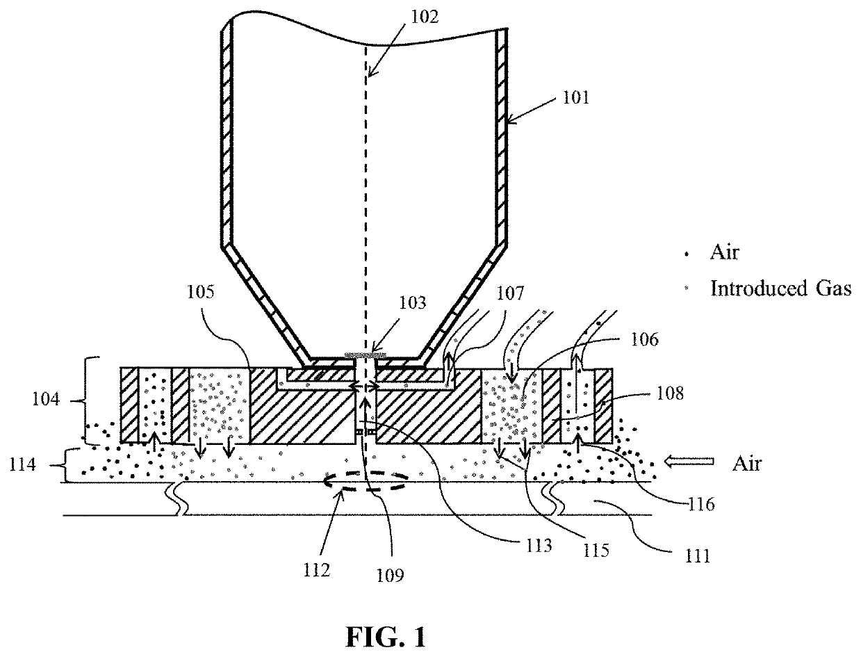
[0044]FIG. 1 is a diagram of a sectional view of a structure of a vacuum condition controlling apparatus 104 according to Embodiment 1 of the disclosure. The top of the vacuum condition controlling apparatus 104 is connected to the bottom of an external electron beam generation instrument. The vacuum condition controlling apparatus is rotationally symmetric, about a central axis. The vacuum condition controlling apparatus may be a cylinder, a rotationally symmetric cuboid, a rotationally symmetric polyhedron, etc. The vacuum condition controlling apparatus has a central axis. The vacuum condition controlling apparatus includes a central channel 113, a first pumping channel 107 connected to an external first pumping system, a gas supplying chamber 106 connected to an external gas supplying system, and at least one second pumping chamber 108 connected to an external second pumping system, the central channel. The first pumping channel, the gas supplying chamber, and the at least one s...
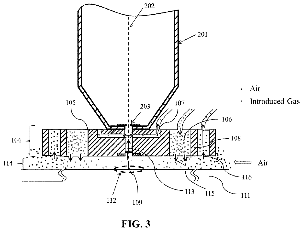
embodiment 2

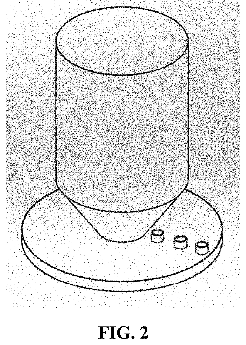
[0060]FIG. 5 is a diagram of an external structure of a vacuum condition controlling apparatus connected to an SEM, according to an embodiment of the disclosure. The top of the vacuum condition controlling apparatus 104 is connected to the bottom of the external SEM. The vacuum condition controlling apparatus is rotationally symmetric, about a central axis. The vacuum condition controlling apparatus may be a cylinder, an rotationally symmetric cuboid, an rotationally symmetric polyhedron, etc. The vacuum condition controlling apparatus has a central axis. The vacuum condition controlling apparatus includes a central channel 113, a first pumping channel 107 connected to an external first pumping system, a gas supplying chamber 106 connected to an external gas supplying system, and at least one second pumping chamber 108 connected to an external second pumping system, the central channel. The first pumping channel, the gas supplying chamber, and the at least one second pumping chamber...

embodiment 3

[0080]Based on the vacuum condition controlling apparatus according to Embodiment 1 and Embodiment 2, an improved vacuum condition controlling apparatus may be provided according to Embodiment 3 of the disclosure. FIG. 6 is a diagram of a sectional view of the vacuum condition controlling apparatus 104. The vacuum condition controlling apparatus in this embodiment may include more than one second pumping chamber 609, and one or more pumping chambers 608 may be added between the first pumping channel and the gas supplying chamber according to Embodiment 1 or Embodiment 2.

[0081]According to an embodiment of the disclosure, an external pumping system connected to a pumping channel may include one or more pumps operating independently to better control a vacuum condition.

[0082]Since the vacuum condition controlling apparatus according to Embodiment 3 is based on that according to Embodiment 1 and Embodiment 2, all features of the vacuum condition controlling apparatus according to Embod...


PUM


Abstract

A vacuum condition controlling apparatus, the top of which is connected with an electron beam generating instrument. The apparatus is rotationally symmetric, comprises the following parts deployed outward from the central axis: the central channel, the first pumping channel, the gas supplying chamber and the at least one pumping chamber. A pressure limiting aperture is deployed near the outlet of the central channel, for keeping the pressure difference between the central channel and the outside environment, and allow the electron beam to go through the central channel; the first pumping channel is connected to the central channel to pump the central channel; the top of the gas supplying chamber is connected to the gas supplying channel to supply gas to the area between the specimen and the apparatus; the top of the second pumping channel is connected to the second pumping channel, to pump the area.

Description

TECHNICAL FIELD[0001]The present disclosure relates to the field of Scanning Electron Microscopes (SEM), and in particular to a vacuum condition controlling apparatus, as well as a system and method for specimen observation.BACKGROUND[0002]Optical microscope (OM) is widely used in scientific research, medical field and industrial production and so on. The advantages of OM observation mainly include: the convenience of specimen preparation, simple operations, adaptability to outside environment, diverse ways of observation and so on. However, when the scale of the objects goes down to less than half of the wavelength (about 200 nm), OM is no longer applicable due to light diffraction. In order to obtain a higher resolution, the scanning electron microscope (SEM) was invented in 1960's, and the resolution of SEM can reach to several nanometers even sub-nanometer scale.[0003]However, there are many disadvantages with SEM, among which the complexities of specimen preparation and rigorou...

Claims


Application Information

Patent Timeline
IPC IPC(8): H01J37/28H01J37/26G01N23/2251
CPCH01J37/28H01J37/261H01J2237/2605H01J2237/188G01N23/2251
Inventor HE, WEILI, SHUAI
Owner FOCUS E BEAM TECH BEIJING CO LTD
Learn More