High-magnetic-flux discrete stator electrical machine

a discrete, stator technology, applied in the direction of magnet circuit shape/form/construction, propulsion system, prevention/reduction of eddy current loss in winding heads, etc., can solve the problems of greater torque and greater magnetic force between stator and rotor pole, and achieve the effect of maximizing the magnetic flux density

Inactive Publication Date: 2020-02-06
STARROTOR CORPORATION
View PDF0 Cites 1 Cited by
  • Summary
  • Abstract
  • Description
  • Claims
  • Application Information

AI Technical Summary

Benefits of technology

[0006]The present disclosure relates to electrical machines and more specifically to electrical machines that do work on moving objects. The present disclosu...

Problems solved by technology

The result is greater magnetic force between ...

Method used


Image

  • High-magnetic-flux discrete stator  electrical machine
  • High-magnetic-flux discrete stator  electrical machine
  • High-magnetic-flux discrete stator  electrical machine

Examples


Embodiment Construction

[0025]The FIGURES described below, and the various embodiments used to describe the principles of the present disclosure in this patent document are by way of illustration only and should not be construed in any way to limit the scope of the disclosure. Those skilled in the art will understand that the principles of the present disclosure invention may be implemented in any type of suitably arranged device or system. Additionally, the drawings are not necessarily drawn to scale.

Definitions

[0026]The following provide definitions for general guidance concerning the present disclosure. These definitions should in no way be used to limit the scope of the invention.

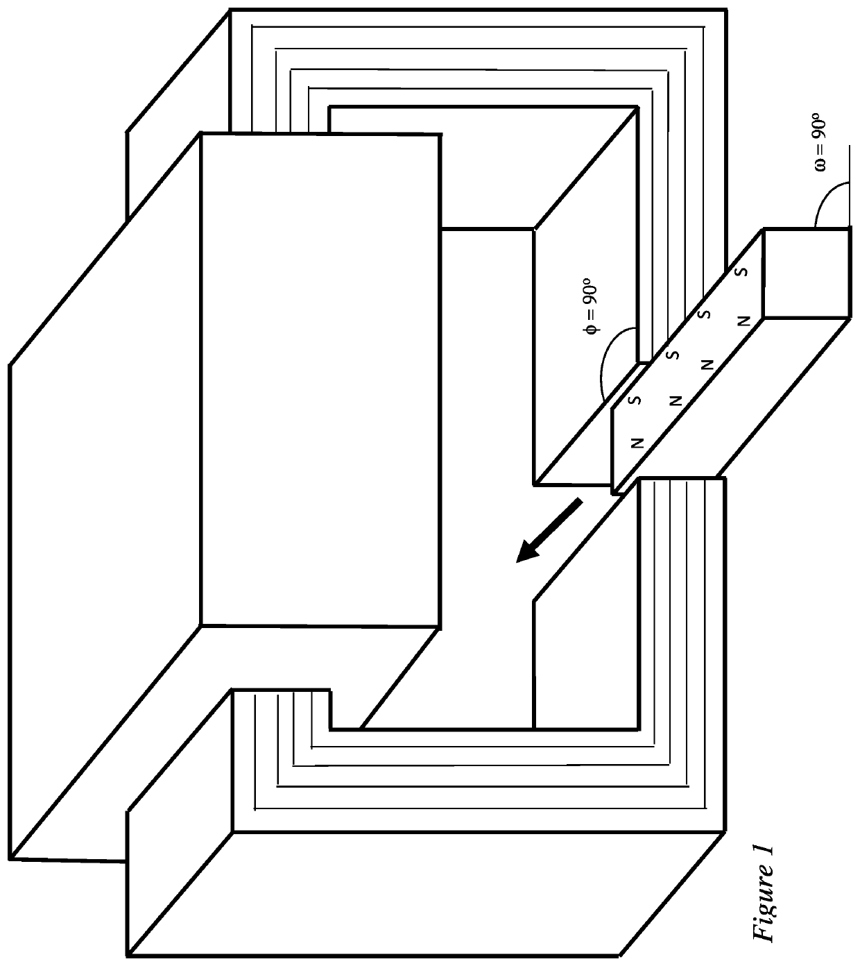
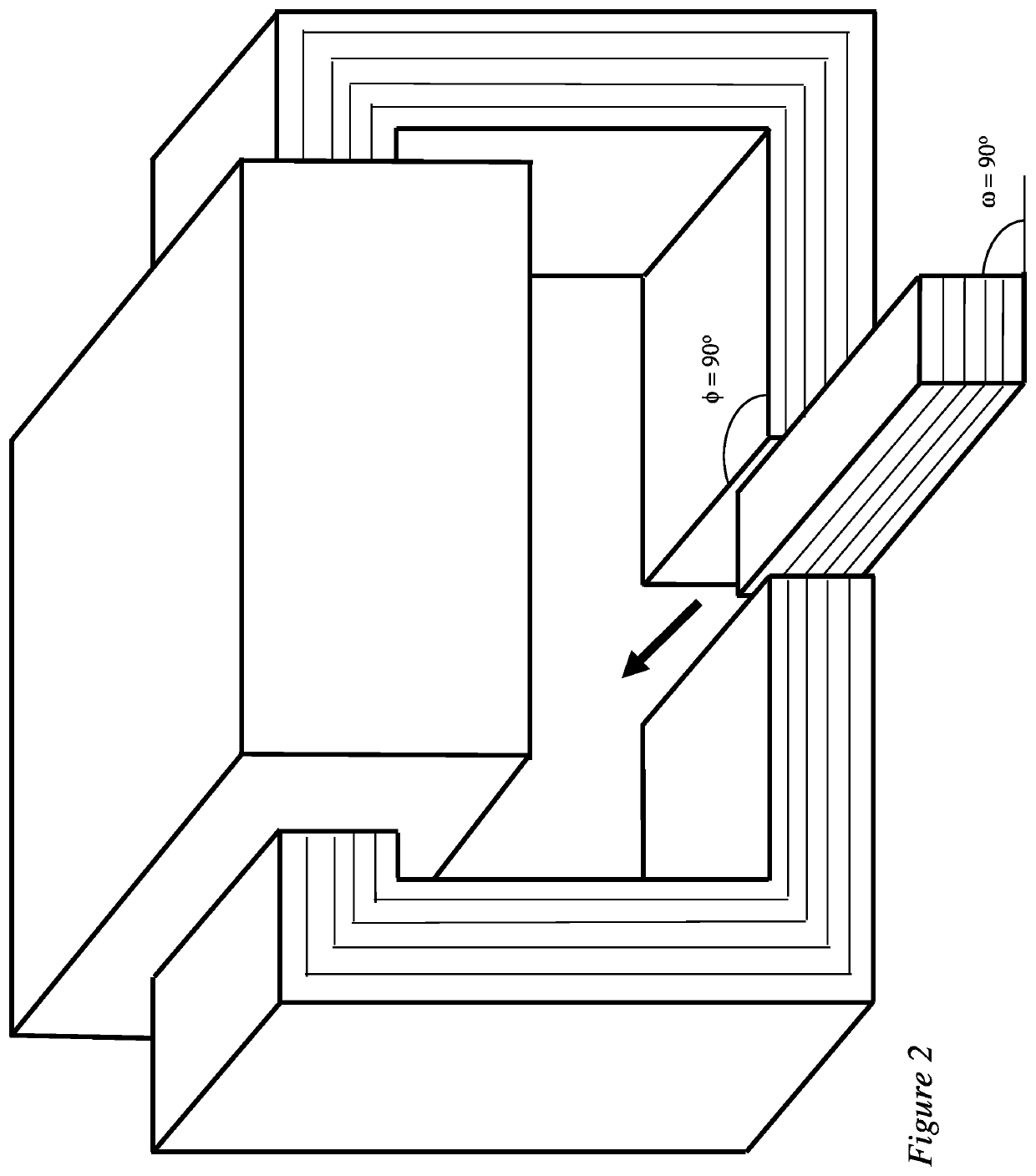
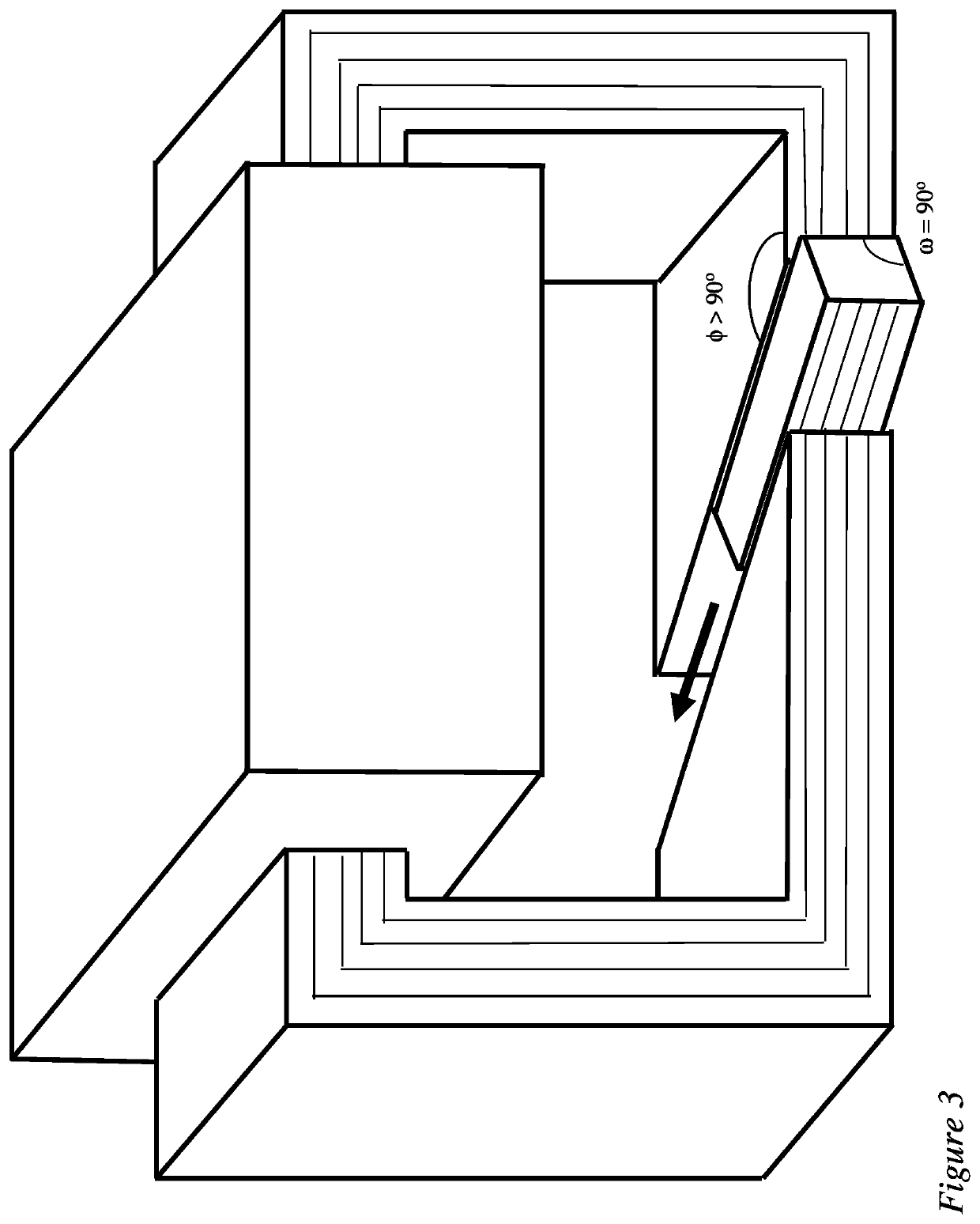
[0027]Magnetic circuit—The magnetic circuit is a closed loop of ferromagnetic material. The magnetic circuit is analogous to a closed loop of pipe.

[0028]Copper coil—The copper coil wraps around the magnetic circuit. In principal, any electrical conductor could be used; however, according to particular embodiments of the disclo...


PUM


Abstract

Electrical machines such as electromagnetic devices rely on the magnetic flux to create the forces required to move the component that transfers the work output of the device. Embodiment of the disclosure achieve this through a unique stator pole to rotor/actuator pole configuration that maximizes the magnetic flux flow across the air gap(s). This is achieved by tilting the air gap in more than one plane with respect to the rotation plane of the rotor.

Description

CROSS-REFERENCE TO RELATED APPLICATIONS[0001]This application is a United States national stage filing of PCT Application No. PCT / US18 / 23292 filed on Mar. 20, 2018, which claims priority to U.S. Provisional Application No. 62 / 474,025 filed on Mar. 20, 2017. This application claims the benefit and priority of U.S. Provisional Application No. 62 / 474,025TECHNICAL FIELD[0002]This invention relates to electric machines and, more particularly, to electromagnetic devices such as rotary motors and generators, and linear actuators and solenoids.BACKGROUND[0003]In generators, input energy is mechanical work and output energy is electrical work. In motors, input energy is electrical work and output energy is mechanical work. Most electrical machines are reversible and can function as either motors or generators.[0004]In motors, electrical energy input imparts motion to one or more components of the machine, such as rotors, solenoids, or actuators. Solenoids and actuators typically move linearl...

Claims


Application Information

Patent Timeline
IPC IPC(8): H02K1/14H02K3/42H02K9/20H02K41/03H02K21/14
CPCH02K41/031H02K21/145H02K9/20H02K1/145H02K3/42H02K2201/12H02K41/03H02K21/24H02K1/143H02K1/141H02K2201/03H02K19/103H02K9/225
Inventor VAN STEENBURG, MICHAEL JHOLTZAPPLE, MARK T
Owner STARROTOR CORPORATION
Why Eureka
Try Eureka