Induction motor

Inactive Publication Date: 2020-11-19
STARROTOR CORPORATION
View PDF0 Cites 0 Cited by
  • Summary
  • Abstract
  • Description
  • Claims
  • Application Information

AI Technical Summary

Benefits of technology

[0006]The present disclosure relates to electrical machines and more specifically to electrical machines that do work on moving objects. The present inventio

Problems solved by technology

The result is greater magnetic force between the

Method used


Image

  • Induction motor
  • Induction motor
  • Induction motor

Examples


Embodiment Construction

[0061]The FIGURES described below, and the various embodiments used to describe the principles of the present disclosure in this patent document are by way of illustration only and should not be construed in any way to limit the scope of the disclosure. Those skilled in the art will understand that the principles of the present disclosure invention may be implemented in any type of suitably arranged device or system. Additionally, the drawings are not necessarily drawn to scale.

Electromagnetism Fundamentals

[0062]The following electromagentism fundamentals are provided for an understanding of certain aspects of embodiments of the disclosure. Such an explanation should not be viewed as limiting the inventive aspects of the disclosure.

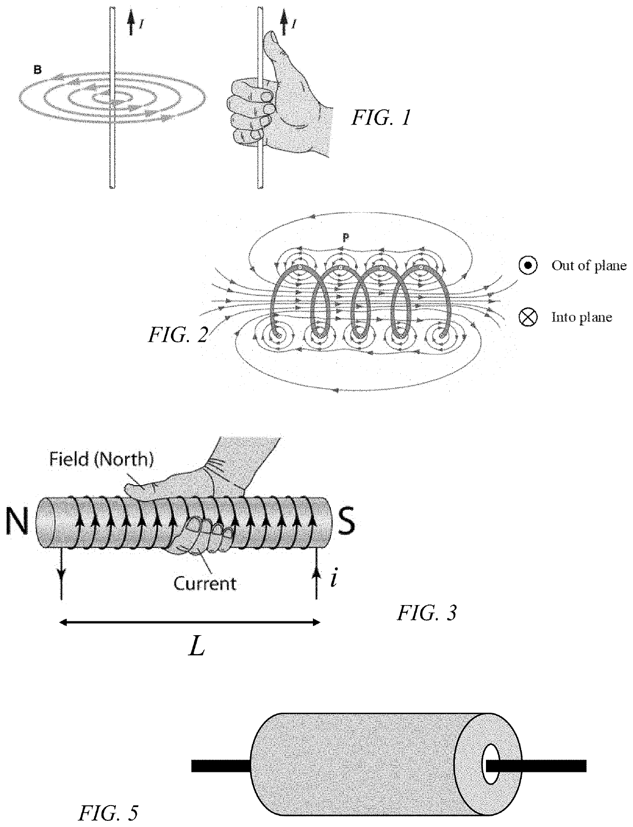
[0063]When current flows through a wire, a magnetic field forms around the wire, for example, as seen in FIG. 1. The right-hand grip rule shows the direction of the magnetic field. By wrapping the wire into a solenoid, the magnetic field lines combine and...


PUM


Abstract

Electrical machines such as electromagnetic devices rely on the magnetic flux to create the forces required to move the component that transfers the work output of the device. The present invention achieves that through a unique stator pole to rotor/actuator pole configuration that maximizes the magnetic flux flow across the air gap(s). This is achieved by tilting the air gap in more than one plane with respect to the rotation plane of the rotor.

Description

CROSS-REFERENCE TO RELATED APPLICATIONS[0001]This application is a United States national stage filing of PCT Application No. PCT / US18 / 60856 filed on Nov. 13, 2018, which claims priority to U.S. Provisional Application No. 62 / 585,454 filed on Nov. 13, 2017. This application claims the benefit and priority of U.S. Provisional Application No. 62 / 585,454.TECHNICAL FIELD[0002]This invention relates to electric machines and, more particularly, to electromagnetic devices such as rotary motors and generators, and linear actuators and solenoids.BACKGROUND[0003]In generators, input energy is mechanical work and output energy is electrical work. In motors, input energy is electrical work and output energy is mechanical work. Most electrical machines are reversible and can function as either motors or generators.[0004]In motors, electrical energy input imparts motion to one or more components of the machine, such as rotors, solenoids, or actuators. Solenoids and actuators typically move linear...

Claims


Application Information

Patent Timeline
IPC IPC(8): H02K1/22H02K1/12
CPCH02K2201/03H02K2201/06H02K1/12H02K1/22H02K1/165H02K17/16H02K19/103H02K21/125H02K41/025H02K2213/03H02K1/06H02K1/28
Inventor VAN STEENBURG, MICHAEL J.HOLTZAPPLE, MARK T.
Owner STARROTOR CORPORATION
Why Eureka
Try Eureka