Armature for an electromotive device

a technology of electromotive devices and armatures, which is applied in the direction of manufacturing stator/rotor bodies, magnetic circuit rotating parts, magnetic circuit shapes/forms/construction, etc., can solve the problems of unsatisfactory inertia, unsatisfactory conductor packing density, and unnecessary losses in permeable materials, so as to maximize the conductor-packing factor and the conductor volume-to-gap ratio

Inactive Publication Date: 2000-08-29
THINGAP
View PDF18 Cites 65 Cited by
  • Summary
  • Abstract
  • Description
  • Claims
  • Application Information

AI Technical Summary

Benefits of technology

It is an object of the invention to provide an ironless core armature for a D.C. motor that would maximize the conductor-packing factor and the conductor volume to gap ratio.

Problems solved by technology

There, however, are a number of problems associated with these designs.
The iron core motors have wire wound through a core of magnetically permeable material and the iron core is cut to minimize the gap but iron core motors have more mass in the armature than ironless core motors creating undesirable inertia problems and involves unnecessary losses in the permeable material.
With typical circular coil wire, the insulation material and air voids inherent in this coil construction make for a less than optimal conductor packing density.
Manufacturers, however, prefer using circular wire due to its lower material and labor cost and ease of manufacturing.
The structure of wire wrapped armatures makes it difficult to produce long small diameter armatures with adequate strength where high RPM produces destructive centrifugal forces.
The amount of electrical conductor in this case is compromised, however, as multiple layers of insulated printed circuit traces tend to result in a thicker armature wall and a diminished conductor packing factor.
Higher electrical resistance results in an undesirable increase in motor heat and energy dissipation, thus causing power losses equal to P=I.sup.2 R. Alternatively, wider printed circuit traces improve motor performance by reducing trace electrical resistance, but allow eddy currents, which reduce the overall gain by again increasing the effective electrical resistance.
This results in a thicker armature structure and a larger magnetic gap.
This PCB construction, unfortunately, does not optimize the configuration of the windings so as to produce optimal torque.
This type device, however, compromises the conductor-packing factor and does not produce optimal torque.
Wire wound conductors of necessity must have wire insulation which decreases the carrier packing factor and thereby the current density per unit area, and thereby the inability to uniformly mount the armature in such manner to cut a maximum of flux lines.
The round cross section of a conventional wire wound armature does not permit such close proximity of current carrier and magnetic field carrier.

Method used


Image

  • Armature for an electromotive device
  • Armature for an electromotive device
  • Armature for an electromotive device

Examples


Embodiment Construction

The following description discloses an enabeling embodiment of the invention and includes the best mode presently contemplated for carrying out the invention. This description is not to be taken in a limiting sense, but is made merely for the purpose of describing the general principles of the invention. Various modifications and variations may be made in the present invention without departing from the scope or spirit of the invention. Features illustrated or described as part of one embodiment can be used in another embodiment to provide yet another embodiment. Thus, it is intended that the present invention covers such modifications and variations as long as they come within the scope of the appended claims and their equivalents.

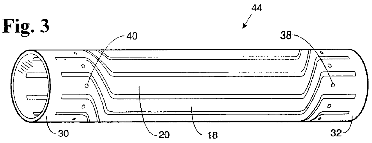
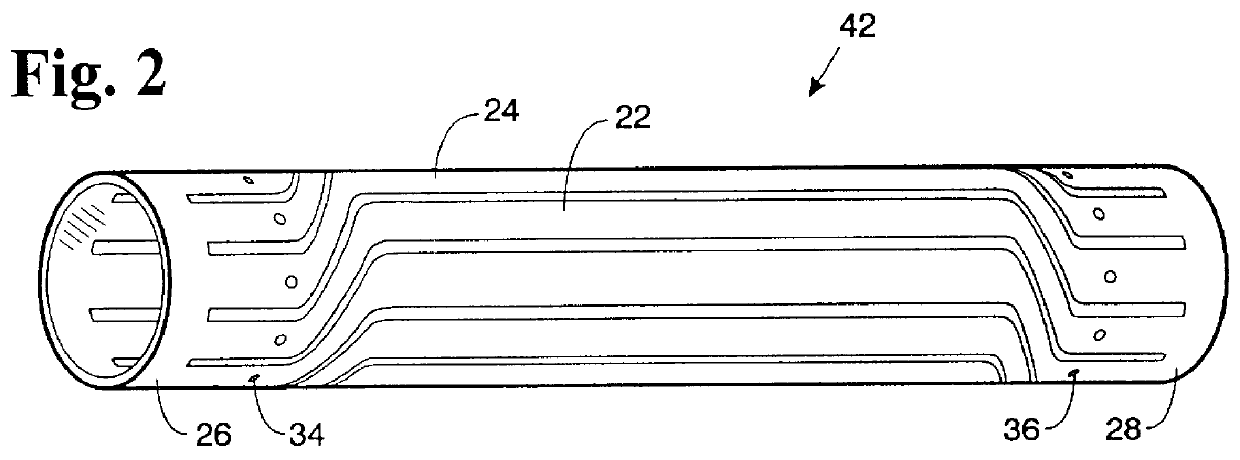
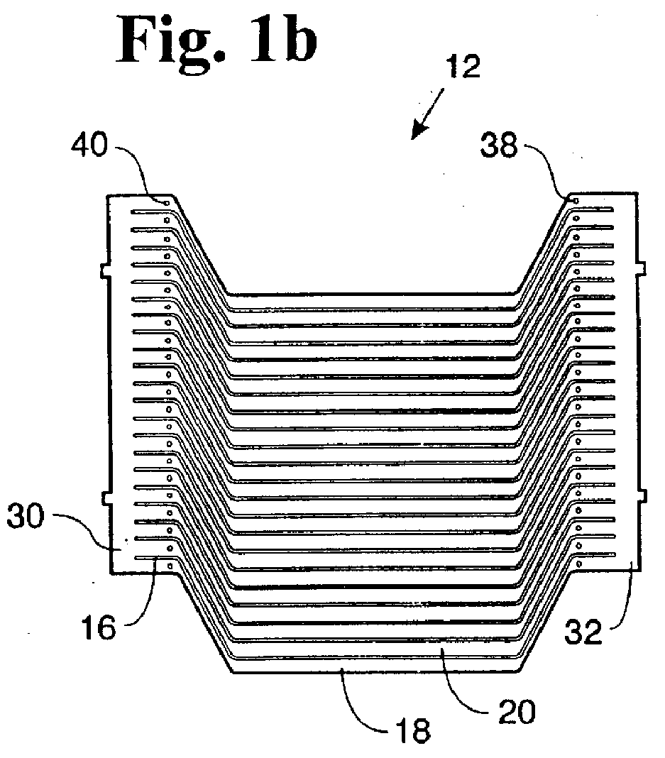
The present invention relates to an ironless core armature for a DC motor having brushes. The novel armature has a conductive coil constructed from a thin pair of nearly mirror image, electrically conductive and precision-machined pieces of bare sheet met...


PUM

PropertyMeasurementUnit
thicknessaaaaaaaaaa
thicknessaaaaaaaaaa
thicknessaaaaaaaaaa

Abstract

An armature for an electric motor is constructed from a pair of precision machined copper plates cut in a pattern to produce a series of axially extending surface conductive bands with each band separated from the other by an insulated cutout. The precision machined plates are rolled to form two telescoping, hollow cylinders with each cylinder having a pattern of conductive bands representing a half-electric circuit. The outer surface of the inner cylinder is wrapped with several layers of fiberglass strands for structural stability and insulation. The fiberglass wrapped inner cylinder is telescoped inside the outer cylinder. The outer surface of the telescoped structure is also wrapped with several layers of fiberglass strands for structural stability. The conductive bands from the outer cylinder being the near mirror image of the conductive bands of the inner cylinder are helically coupled to form a complete electrical circuit. The resulting tubular structure is encapsulated in a potting material for further structural stability and insulation. The result is a freestanding ironless core inductive armature coil for a DC motor with brushes. The armature also has a commutator, which is mounted at one end of the coil and is in electrical contact with the helically coupled conductive bands. An insulated flywheel and shaft assembly is mounted inside the coil with the flywheel behind the commutator for motor mounting and operation.

Description

1. Field of the InventionThe present invention relates to electromotive devices and more particularly to an ironless core armature for an electric motor.2. Description of the Prior ArtElectric motor manufacturers and in particular DC motor manufacturers have traditionally employed wire winding or printed circuit coil techniques to fabricate ironless core armatures, which move in a magnetic flux air gap. There, however, are a number of problems associated with these designs. Ironless core motors are typically run with a larger gap than conventional iron core designs. The iron core motors have wire wound through a core of magnetically permeable material and the iron core is cut to minimize the gap but iron core motors have more mass in the armature than ironless core motors creating undesirable inertia problems and involves unnecessary losses in the permeable material.In the wire winding case, the insulated wire is wrapped in a multilayer configuration to form the current carrying coi...

Claims


Application Information

Patent Timeline
Patent Type & Authority Patents(United States)
IPC IPC(8): H02K3/26H02K3/04H02K13/04H02K3/34H02K3/47H02K15/02H02K15/04H02K15/12H02K23/58
CPCH02K3/26H02K3/47H02K13/04H02K15/02H02K15/12Y10S310/06Y10T29/4902Y10T29/49169Y10T29/49146Y10T29/49012Y10T29/49009Y10T29/49073Y10T29/49071Y10T29/53839
Inventor GRAHAM, GREGORY S.YANKIE, GERALD W.
Owner THINGAP
Why Eureka
Try Eureka