Fire-blocking insulation blanket

a technology of insulation blankets and fire-blocking blankets, which is applied in the field of aircraft-type insulation blankets, can solve the problems of reducing the effectiveness of fire-blocking insulation blankets, fuel spilling from aircraft and igniting, and perishing in fire, so as to reduce the cost of retrofitting existing aircraft, improve fire-blocking properties, and protect the

Inactive Publication Date: 2002-03-19
ORCON CORP
View PDF6 Cites 127 Cited by
  • Summary
  • Abstract
  • Description
  • Claims
  • Application Information

AI Technical Summary

Benefits of technology

A fire-blocking insulation blanket constructed and installed according to the present invention will remain secured in place for at least two minutes, and preferably for more than five minutes, when subjected to the full-scale test described in the report titled "Full-Scale Evaluation of Aircraft Fuel Fire Bumthrough Resistance Improvements," published by the United States Department of Transportation, Federal Aviation Administration (FAA), Fire Safety Section in January, 1999. In the same test, no gap permitting flame penetration will form between the aircraft frame members and the edges of a blanket constructed and installed according to the present invention for at least two minutes, and preferably for more than five minutes. Because the FAA test is designed to simulate realistic conditions during a post-crash fuel fire, it is anticipated that blankets according to the present invention will provide superior protection from flame penetration under real-world conditions.
Another advantage offered by the present invention is reducing the cost of retro fitting existing aircraft with insulation blankets having improved fire-blocking properties. According to FAA regulations, every modification to an existing aircraft must be documented. In the case of insulation blankets, any modification that requires changes to design drawings will typically have to be incorporated into over a thousand drawings for every airplane model. Therefore, providing an improved insulation blanket that may be fabricated without requiring changes to the original blanket drawings can result in significant cost savings. The present invention may be practiced by placing a layer of fire blocking material adjacent to the outboard side of the insulation blanket. The fire blocking layer may be incorporated into one of the two pieces of polymer protective covering films typically used to encase the lofted insulation, or it may be separate from the protective covering. The fire blocking layer will typically have the same or similar geometry as the outboard piece of protective covering film. Therefore it may be cut from the same template as the original piece of protective covering. To document the change, the aircraft operator need only revise the bill of materials and part number for the insulation blankets to specify the replacement film incorporating a fire-blocking material. Therefore, the more time-consuming changes to the geometric blanket patterns, including drawings and templates, may be avoided.
Blankets constructed and installed according to the present invention are especially useful for providing economical and effective fire-blocking insulation for aircraft. However, such blankets may also be used to provide fire-blocking insulation to any structure, such as a ship, bus, or building, that utilizes frame members that are (a) sufficiently fire-resistant to hold a fire-blocking blanket in place for the desired period of time, (b) adjacent to the exterior of the space which is to be protected from fire, and (c) configured to permit installation of insulation blankets between and attached to adjacent frame members. It is anticipated that blankets according to the present invention will be advantageous whenever fire-blocking replacements for regular (non-fire-blocking) insulation blankets are needed. In addition, blankets according to the present invention will be especially advantageous as replacement blankets whenever there is a need to conserve use of relatively costly and / or heavy fire-blocking material, because efficient use is made of a minimum amount of fire-blocking material.

Problems solved by technology

Survivable post-crash fuel fires have occurred in the past after crash landings that were not severe enough to cause the fuselage to be destroyed upon impact, but were severe enough to cause fuel to spill from the aircraft and ignite.
If the fuel fire penetrates the fuselage interior too quickly, the occupants will be overcome by smoke and heat before they can evacuate the aircraft, and will perish in the fire.
Current methods commonly in use for securing insulation blankets to aircraft frame members will reduce the effectiveness of fire-blocking insulation blankets.
The selvedge currently used to secure the insulation blanket will rapidly melt or bum when exposed to the heat of a fuel fire.
Current insulation blankets and methods of attachment will not provide the desired duration and quality of attachment when exposed to a fuel fire.

Method used


Image

  • Fire-blocking insulation blanket
  • Fire-blocking insulation blanket
  • Fire-blocking insulation blanket

Examples


example 1

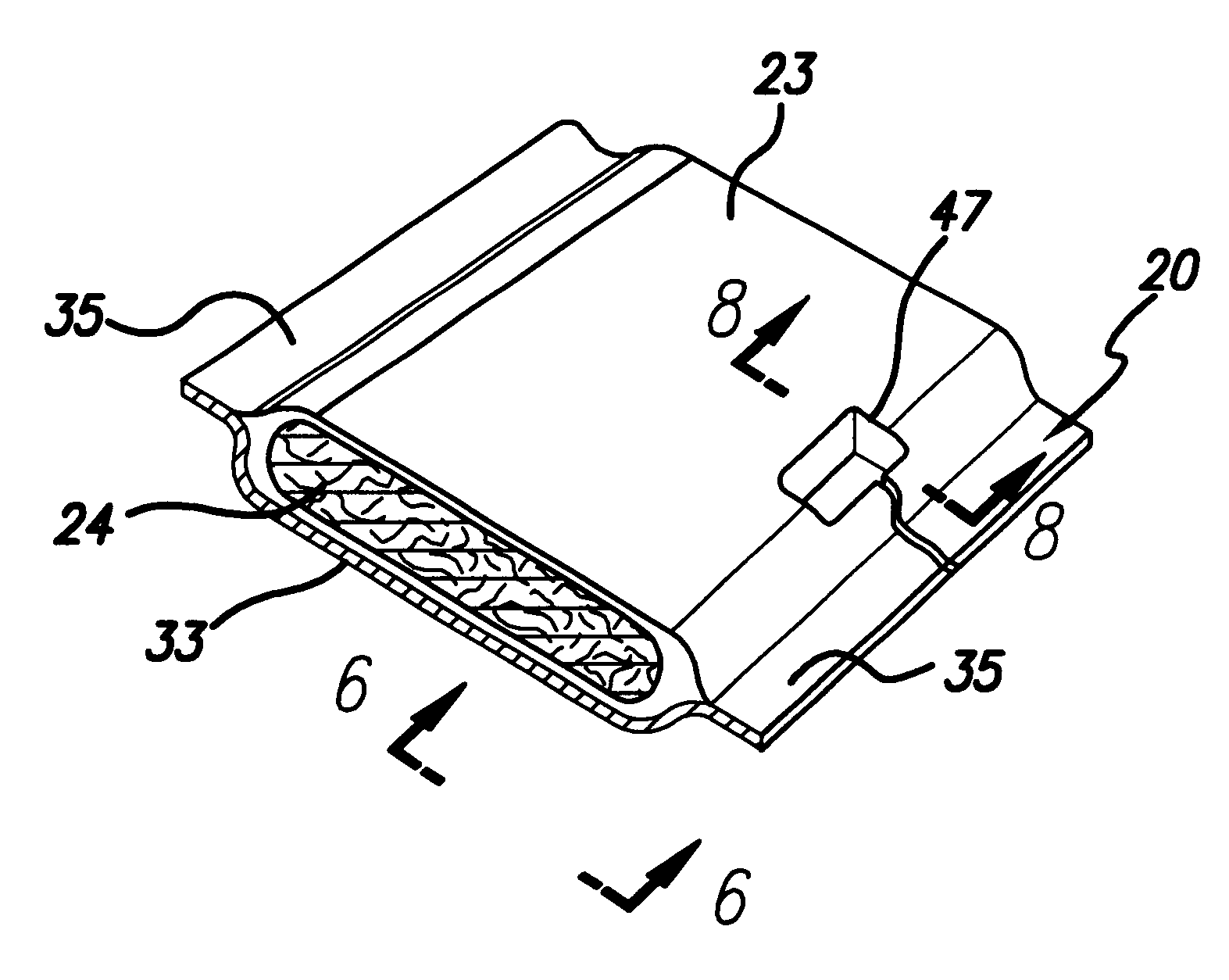
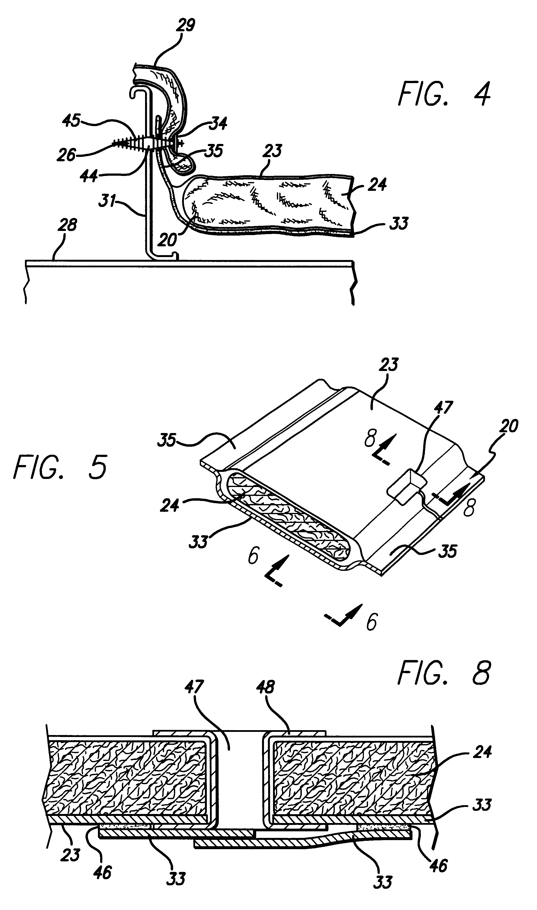
Blanket Construction.

A piece of lofted insulation comprised of 2 inch thick 0.42 pcf MICROLITE.TM. AA Fiberglass from Johns Manville Corporation of Denver, Colorado was cut to the dimensions approximately 20 inches wide and 36 inches long. A piece of fire-blocking material comprised of CURLON.RTM. OB-5250G, nominally 0.25 inches thick, from ORCON Corporation of Union City, California, was cut to dimensions approximately 28 inches wide and 36 inches long. Two pieces of protective covering comprised of reinforced polyimide film available under the trade name ORCOFILM.TM. KN-80 from ORCON Corporation of Union City, Calif. were cut to dimensions approximately 32 inches wide and 40 inches long. The lofted insulation and fire-blocking material were stacked and centered with respect to each other, leaving 4 inches of fire-blocking material protruding from each edge of the lofted insulation. The stack of lofted insulation and fire-blocking material was placed between the two pieces of cover...

example 2

Screening Test for Fire Blocking Materials

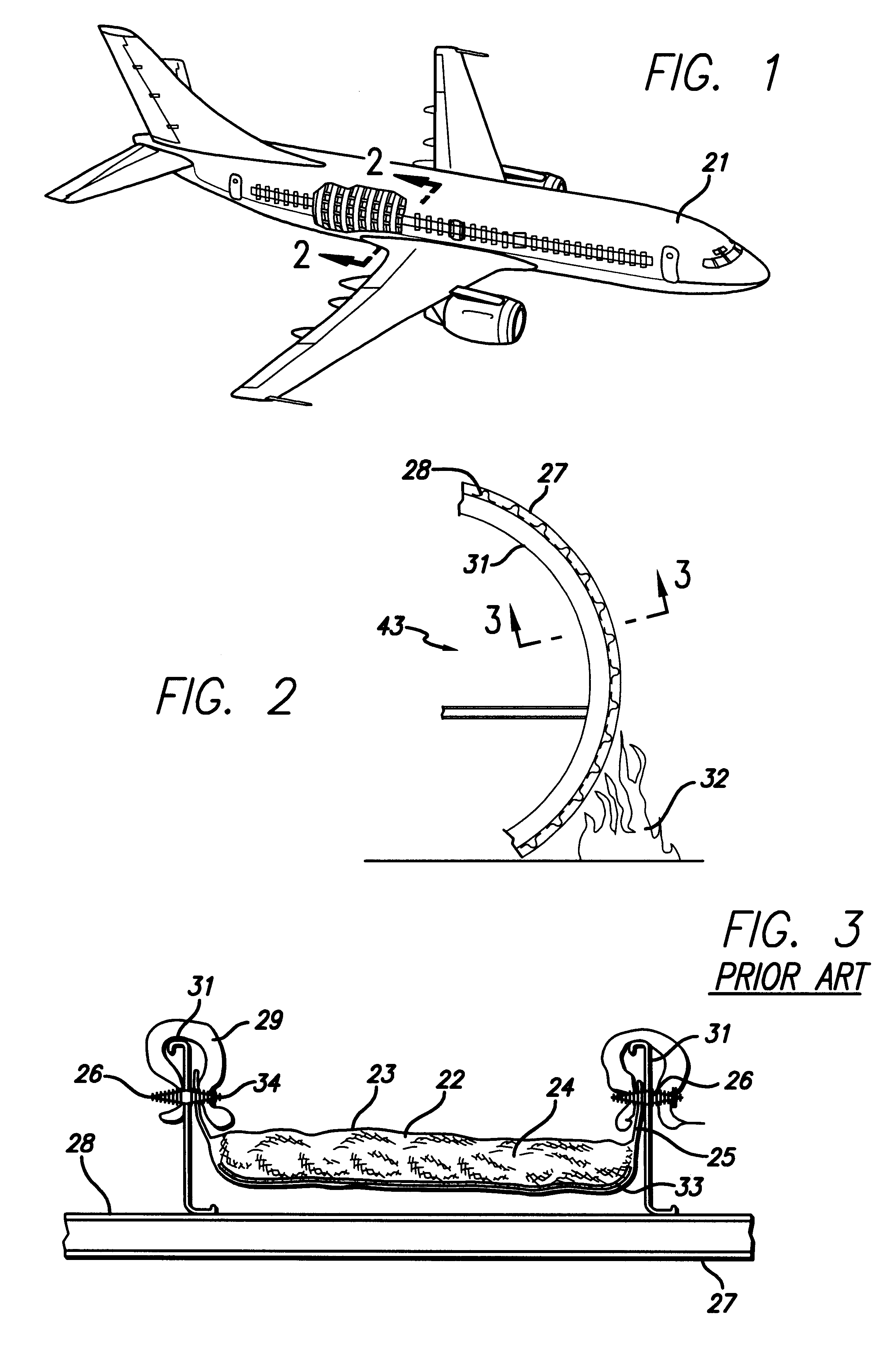
Materials were screened for fire blocking properties using the following laboratory scale test. A specimen holder was constructed from two pieces of aluminum sheet material approximately 0.10 inch thick. Each piece was approximately 13 inches square. A circular hole approximately eight inches in diameter was cut in the center of each piece of sheet aluminum. One of the pieces was mounted horizontally to laboratory test stands using laboratory clamps, about 24 inches from the base of the test stands inside of a laboratory hood. An adjustable propane torch, Model TL-44 from TURBOTORCH.RTM. of Denton, Tex. , was connected to a compatible propane bottle with a shut-off valve. The torch was mounted on a laboratory stand. The nozzle was mounted using a laboratory clamp so that the nozzle of the torch was directed vertically upwards, underneath and directed at the center of the hole in the aluminum piece. The upper end of the torch nozzle was about...


PUM

PropertyMeasurementUnit
densityaaaaaaaaaa
densityaaaaaaaaaa
densitiesaaaaaaaaaa

Abstract

An insulation blanket is disclosed that contains fire-blocking materials for preventing rapid penetration of fire into an aircraft fuselage in case of a fire outside the aircraft. The insulation blanket contains at least one layer of fiberglass or other thermal-acoustic insulation material without fire-blocking properties, and one or more layers of fire-blocking material. The fire blocking material is wider than the thermal-acoustic insulation so that it may be folded against and attached to adjacent structural frame members of the fuselage. In the alternative, a thermal-acoustic insulation material is used that has fire-blocking properties instead of the separate layers of fire-blocking and thermal-acoustic insulation materials. A method for installing insulation blankets according to the present invention is disclosed, whereby a fire-blocking insulation portion of the blanket is folded against and attached to frame members of the aircraft using attachment posts or spring clips.

Description

1. Field of the InventionThis invention relates to insulation blankets for providing thermal and acoustic insulation for aircraft. More particularly, this invention relates to insulation blankets that contain fire-blocking materials for preventing rapid penetration of fire into an aircraft fuselage in case of a fire outside the aircraft.2. Description of the Related ArtThe passenger cabins of commercial passenger airplanes are insulated from temperature extremes and noise by the use of thermal / acoustic insulation blankets. Examples of such insulation blankets are described in U.S. Pat. No. 5,108,821 (Dooley, et. al.) and in U.S. Pat. No. 5,624,726 (Sanocki et. al.). Such insulation blankets are typically placed adjacent to the interior skin of the aircraft fuselage, between fuselage frame members that are typically parallel and spaced at regular intervals along the length of the fuselage. The insulation blankets are typically constructed to a uniform width to fit snugly between the ...

Claims


Application Information

Patent Timeline
Patent Type & Authority Patents(United States)
IPC IPC(8): B64C1/00B64C1/40
CPCB64C1/40Y10S428/92Y10S428/921Y10T428/2419Y10T428/237Y10T428/23Y10T428/24777Y10T442/2631Y10T442/198Y10T442/191Y10T442/2975Y10T442/2992
Inventor SMITH, SHERMAN S.
Owner ORCON CORP
Why Eureka
Try Eureka