Optical sensor and image forming apparatus
a technology of optical sensors and image forming equipment, which is applied in the direction of photometry using electric radiation detectors, optical radiation measurement, instruments, etc., can solve the problems of optical sensors, difficult downsizing, and the image of mixed colors does not become the desired tin
- Summary
- Abstract
- Description
- Claims
- Application Information
AI Technical Summary
Benefits of technology
Problems solved by technology
Method used
Image

Examples
first embodiment
Overall Configuration
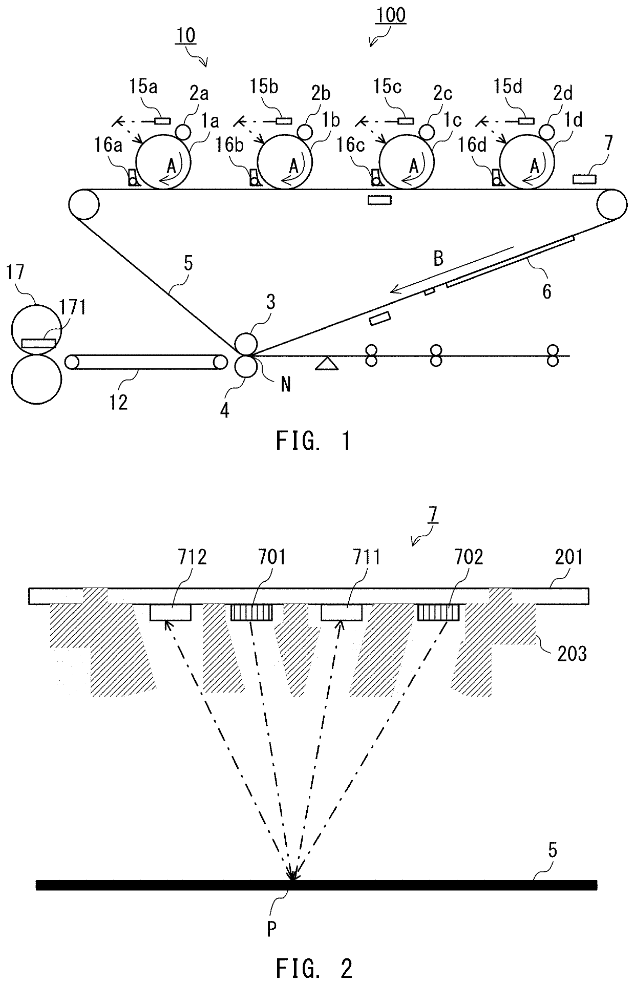
[0031]FIG. 1 is a schematic cross-sectional view of an image forming apparatus 100 according to a first embodiment of the present disclosure. The image forming apparatus 100 includes photosensitive drums 1a to 1d, charging devices 2a to 2d, exposure devices 15a to 15d, developing devices 16a to 16d, an intermediate transfer belt 5, a belt support roller 3, a transfer roller 4, and a fixing device 17. In the following description, the photosensitive drums 1a to 1d, the charging devices 2a to 2d, the exposure devices 15a to 15d, and the developing devices 16a to 16d are referred to as an “image forming unit 10” configured to form toner images of respective colors of yellow (Y), cyan (C), magenta (M), and black (K). The letter “a” suffixed to the reference signs represents a configuration for forming the yellow image. The letter “b” suffixed to the reference signs represents a configuration for forming the cyan image. The letter “c” suffixed to the reference signs ...
second embodiment
Overall Configuration
[0095]A configuration of an image forming apparatus according to a second embodiment of the present disclosure is the same as the configuration of the image forming apparatus 100 according to the first embodiment exemplified in FIG. 1, and hence a description thereof is omitted.
Optical Sensor
[0096]FIG. 17 is a schematic view of a main part of the optical sensor 7. The optical sensor 7 according to the second embodiment is different from the optical sensor 7 according to the first embodiment illustrated in FIG. 2 in array of elements. In the optical sensor 7 according to the second embodiment, light emitting elements and light receiving elements are arranged on the substrate 201 in the following order: the first LED 701, the first PD 711, the second PD 712, and the second LED 702. In other words, the first PD 711 and the second PD 712 are located between the first LED 701 and the second LED 702. Further, the optical sensor 7 includes a housing 203, in which light...
PUM
 Abstract
Description
Claims
Application Information
 - R&D
- Intellectual Property
- Life Sciences
- Materials
- Tech Scout
- Unparalleled Data Quality
- Higher Quality Content
- 60% Fewer Hallucinations
Browse by: Latest US Patents, China's latest patents, Technical Efficacy Thesaurus, Application Domain, Technology Topic, Popular Technical Reports.
© 2025 PatSnap. All rights reserved.Legal|Privacy policy|Modern Slavery Act Transparency Statement|Sitemap|About US| Contact US: help@patsnap.com