A Collapsible Intermodal Container and a Collapsible Intermodal Container Assembly

Active Publication Date: 2020-03-05
SPECTAINER PTY LTD
View PDF0 Cites 2 Cited by
  • Summary
  • Abstract
  • Description
  • Claims
  • Application Information

AI Technical Summary

Benefits of technology

The patent describes a collapsible intermodal container that can be easily moved and erected. It includes a lifting system attached to the side wall and a bracket to secure the container in the erected position. The front and rear end assemblies of the container are also engaged with other containers to provide support. The technical effect is that the container is easy to move and secure, and can be supported by other containers without needing additional hardware or manual labor.

Problems solved by technology

In international trade, there is usually a trade imbalance between an exporting country and an importing country.
However, once the intermodal containers arrive at the importing country and the goods are unloaded, the intermodal containers are transported back to the exporting country in an empty state for reuse due to the trade imbalance.
The transportation of empty intermodal containers is highly inefficient and involves significant costs, especially in relation to fuel, handling, and storage.
Also, in domestic logistics activities, similar imbalances and thereby similar disadvantages can occur.

Method used


Image

  • A Collapsible Intermodal Container and a Collapsible Intermodal Container Assembly
  • A Collapsible Intermodal Container and a Collapsible Intermodal Container Assembly
  • A Collapsible Intermodal Container and a Collapsible Intermodal Container Assembly

Examples


first embodiment

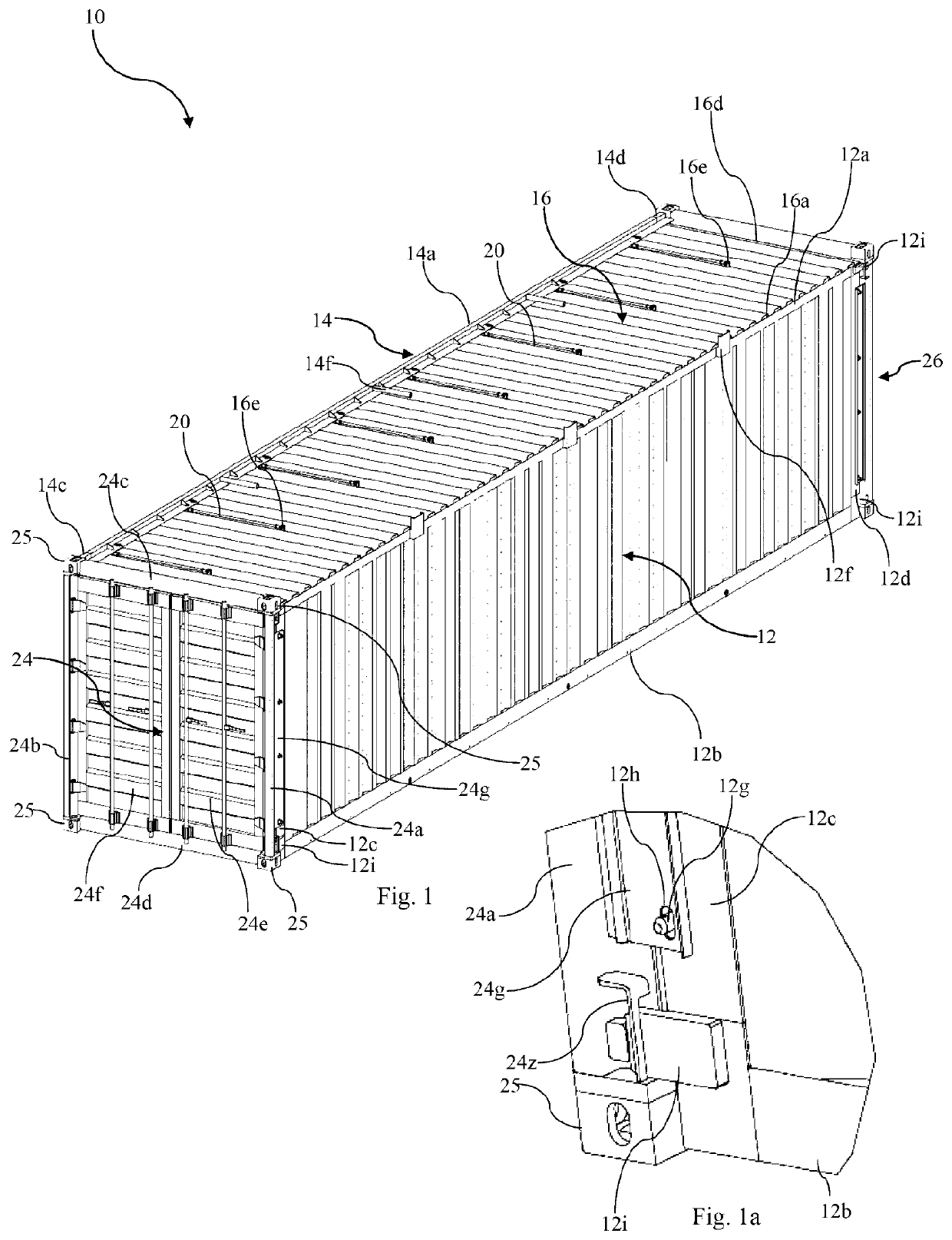
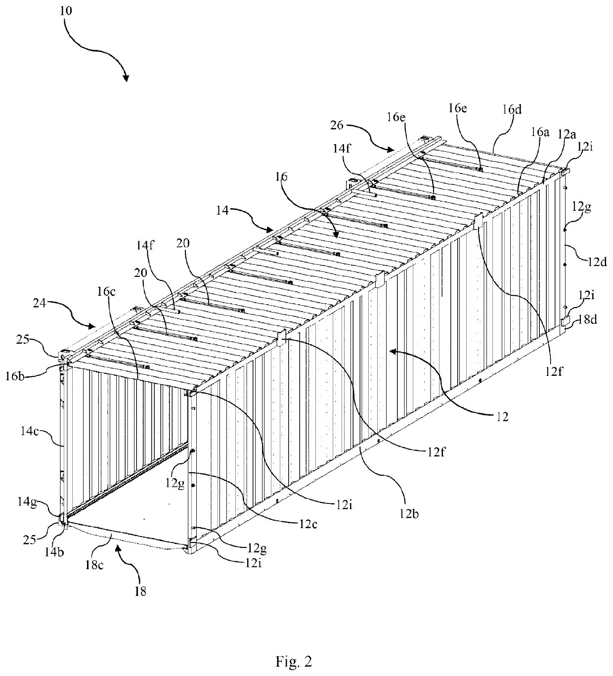
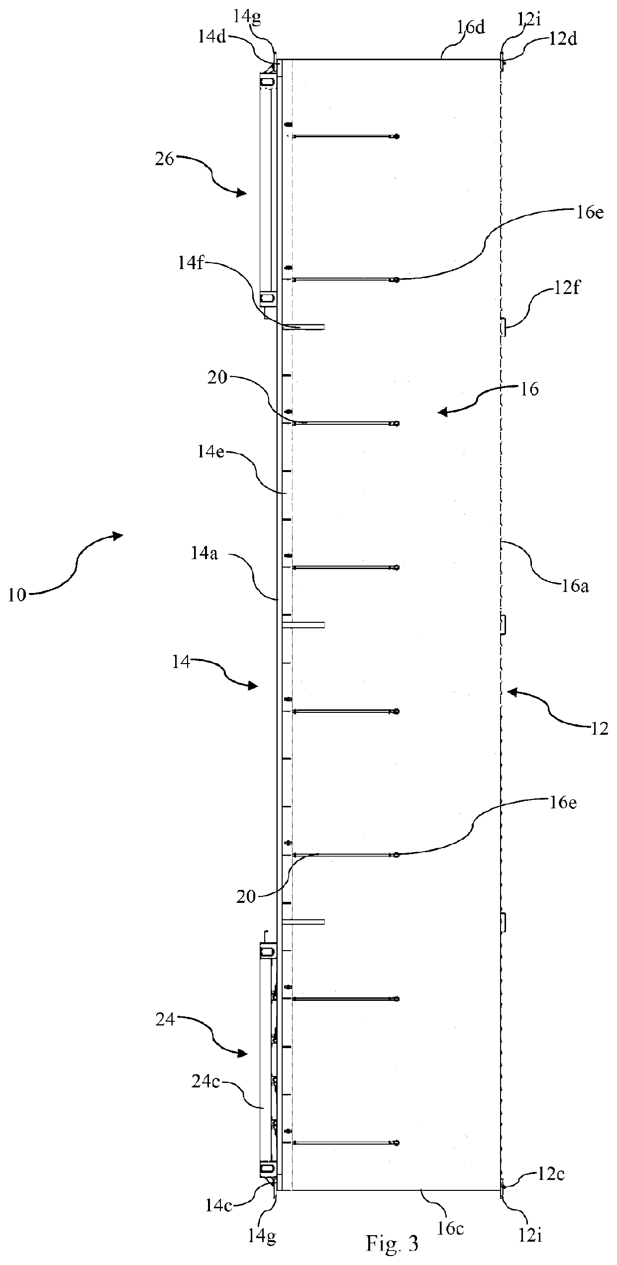
[0079]FIGS. 1 to 12 of the accompanying drawings show a collapsible intermodal container 10. The container 10 comprises a right side wall 12 and a left side wall 14. The side walls 12, 14 oppose each other and are substantially parallel to each other. Each of the side walls 12, 14 is formed from a rectangular corrugated steel panel which is surrounded by a rectangular steel frame. The right side wall 12 is defined by an upper longitudinal end 12a, a lower longitudinal end 12b, a front end 12c and a rear end 12d. The left side wall 14 is defined by an upper longitudinal end 14a, a lower longitudinal end 14b, a front end 14c and a rear end 14d.

[0080]As seen in FIG. 4, the right side wall 12 has a lower flange 12e which is disposed at the lower longitudinal end 12b and extends towards the lower longitudinal end 14b of the left side wall 14. The right side wall 12 further has three stop members 12f that are disposed at the upper longitudinal end 12a and are evenly spaced apart between ...

second embodiment

[0101]FIGS. 13 to 21 of the accompanying drawings show a collapsible intermodal container 10′. Features of the collapsible intermodal container 10′ that are substantially identical or similar to those of the collapsible intermodal container 10 are provided with the same reference numerals.

[0102]The collapsible intermodal container 10′ is substantially identical to the collapsible intermodal container 10. However, as best seen in FIG. 13, the collapsible intermodal container 10′ further comprises four lifting systems 30a, 30b, 30c, 30d for use in configuring the container 10′ to the erected configuration. Each of the lifting systems 30a, 30b, 30c, 30d includes an elongate flexible strap 32 for use in lifting the upper wall 16 into position when configuring the container 10′ to the erected configuration. For this reason, the lifting systems 30a, 30b, 30c, 30d are also referred to herein as strap systems 30a, 30b, 30c, 30d, and one of these strap systems 30a will now be described in gr...

third embodiment

[0109]As can be seen in FIGS. 22 and 23, this third embodiment of a collapsible intermodal container 10″ differs in relation to the closure mechanism for locating and securing the front and rear door assemblies 24, 26 in the closed position when the collapsible intermodal container 10″ is being configured to the erected configuration. In this embodiment, instead of a closure mechanism comprising a flap member 24g hingedly attached to the right upright member 24a of the front door assembly 24, with openings 24h adapted to receive respective protrusions 12g on the front end 12c of the right side wall 12, the closure mechanism comprises two closure levers 24i fixed to the front end 12c of the right side wall 12, spaced apart as upper and lower closure levers 24i. Each closure lever 24i has a handle 24j that is operable to extend a latch arm 24k for engaging a catch 24m that is fixed to the upright member 24a of the front door assembly 24 and aligned with the latch arm 24k. The handle 2...


PUM


Abstract

The present invention provides a collapsible intermodal container (10, 10′, 10″), comprising: first and second opposing parallel side walls (12, 14), the first side wall (14) being connected to the second side wall (12) such that the collapsible intermodal container is configurable between an erected configuration in which the first and second side walls (12, 14) are spaced apart by a first distance (D1) to define an interior for storing goods, and a collapsed configuration in which the first and second side walls (12, 14) are spaced apart by a second distance (D2) which is less than the first distance (D1). The collapsible intermodal container (10, 10′, 10″) further comprises front and rear end assemblies (24, 26) for closing front and rear ends of the container in the erected configuration and for controlling access to the interior, each of the front and rear end assemblies (24, 26) being hingedly attached to the first side wall (14). When the collapsible intermodal container (10, 10′, 10″) is in the erected configuration, the front and rear end assemblies (24, 26) are engageable with the second side wall (12) to secure the first side wall (14) with respect to the second side wall (12), and, when the collapsible intermodal container (10, 10′, 10″) is in the collapsed configuration, the front and rear end assemblies (24, 26) are engageable with at least a further collapsible intermodal container (10, 10′, 10″) to secure the first side wall (14) with respect to the further collapsible intermodal container (10, 10′, 10″). The invention further provides a collapsible intermodal container assembly, comprising: first and second collapsible intermodal containers (10, 10′, 10″) according to the present invention, each of the first and second collapsible intermodal containers (10, 10′, 10″) being in the collapsed configuration. The front and rear end assemblies (24, 26) of the first collapsible intermodal container (10, 10′, 10″) are engaged with the first side wall (14) of the first collapsible intermodal container and the second side wall (12) of the second collapsible intermodal container such that the first side wall (14) of the first collapsible intermodal container is secured to the second side wall (12) of the second collapsible intermodal container.

Description

FIELD[0001]The present invention relates to a collapsible intermodal container and a collapsible intermodal container assembly.BACKGROUND[0002]Intermodal containers, also known as ISO containers or shipping containers, are used to store a wide range of goods for transportation. In general, an intermodal container is a rectangular steel box with doors on either end to provide access to the interior in which goods are stored. The intermodal container also has a casting on each corner for engagement with twistlocks and / or bridge clamps to lock the intermodal container into place or interlock with other intermodal containers when stacked together.[0003]In international trade, there is usually a trade imbalance between an exporting country and an importing country. Typically, intermodal containers are loaded with goods at the exporting country and then transported to the importing country. However, once the intermodal containers arrive at the importing country and the goods are unloaded,...

Claims


Application Information

Patent Timeline
IPC IPC(8): B65D88/52
CPCB65D88/524B65D88/522Y02W30/80B65D88/52B65D88/121
Inventor PRESS, NICHOLAS OLIVERTILLER, ROBERT BRUCEHILL, STEPHEN RICHARDSALMON, DANIEL GRAHAMHERSHKOVITZ, LIOR
Owner SPECTAINER PTY LTD
Why Eureka
Try Eureka