Process and device for measuring wear of a refractory lining of a receptacle intended to contain molten metal
Active Publication Date: 2020-03-05
ARCELORMITTAL INVESTIGACION Y DESARROLLO SL
View PDF0 Cites 3 Cited by
Summary
Abstract
Description
Claims
Application Information
AI Technical Summary
This helps you quickly interpret patents by identifying the three key elements:
Problems solved by technology
Method used
Benefits of technology
Benefits of technology
The patent is about a process to accurately measure the wear of the refractory lining in a more efficient way. The process involves using two laser scanners located in a water-tight and protected box. The box has a main part with an opening and a closing system that can be moved between an open position to a closed position. The laser scanners scan the refractory lining through the opening when the closing system is open. The technical effect of this process is that it provides a more accurate measurement of wear on refractory linings, which can help improve efficiency and prolong the lifespan of the refractory materials.
Problems solved by technology
However, the refractory lining is subject to wear or deposits coming from the molten steel.
However, this method has proven somewhat difficult, due to the environment of the receptacle in terms of dust and temperature, and non-quantitative.
However, due to the shape of the receptacle, internal geometrical constraints of the receptacle, and the fact that the laser scanner cannot be too close to a receptacle that is still hot, the laser scanner usually does not allow obtaining a full view of the surface of interest.
This makes the whole process complex and the global image not so accurate, especially for a differential analysis over time such as wear control.
Method used
Image
Click on the blue label to locate the original text in one second.
Reading with bidirectional positioning of images and text.
Examples
first embodiment
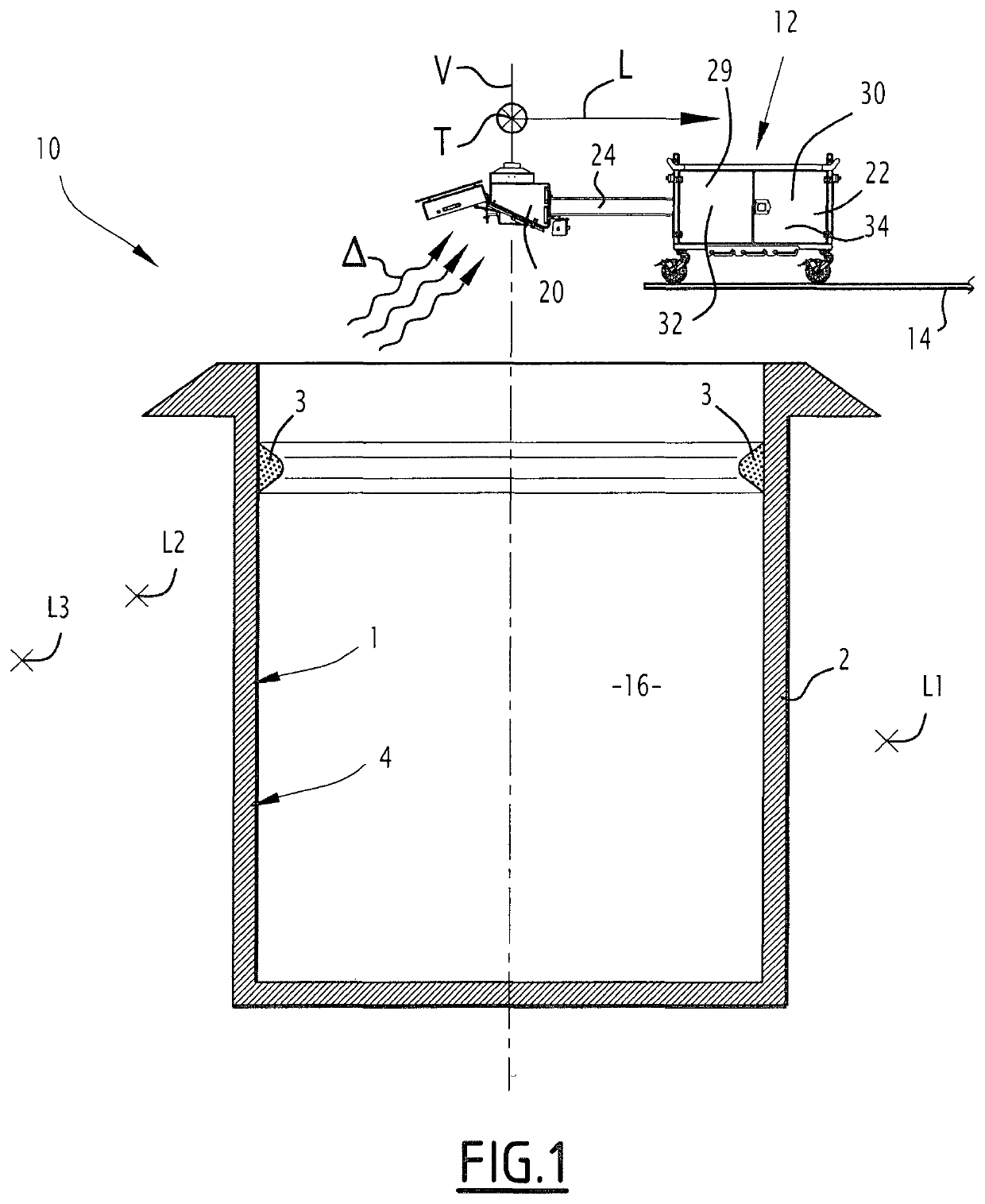
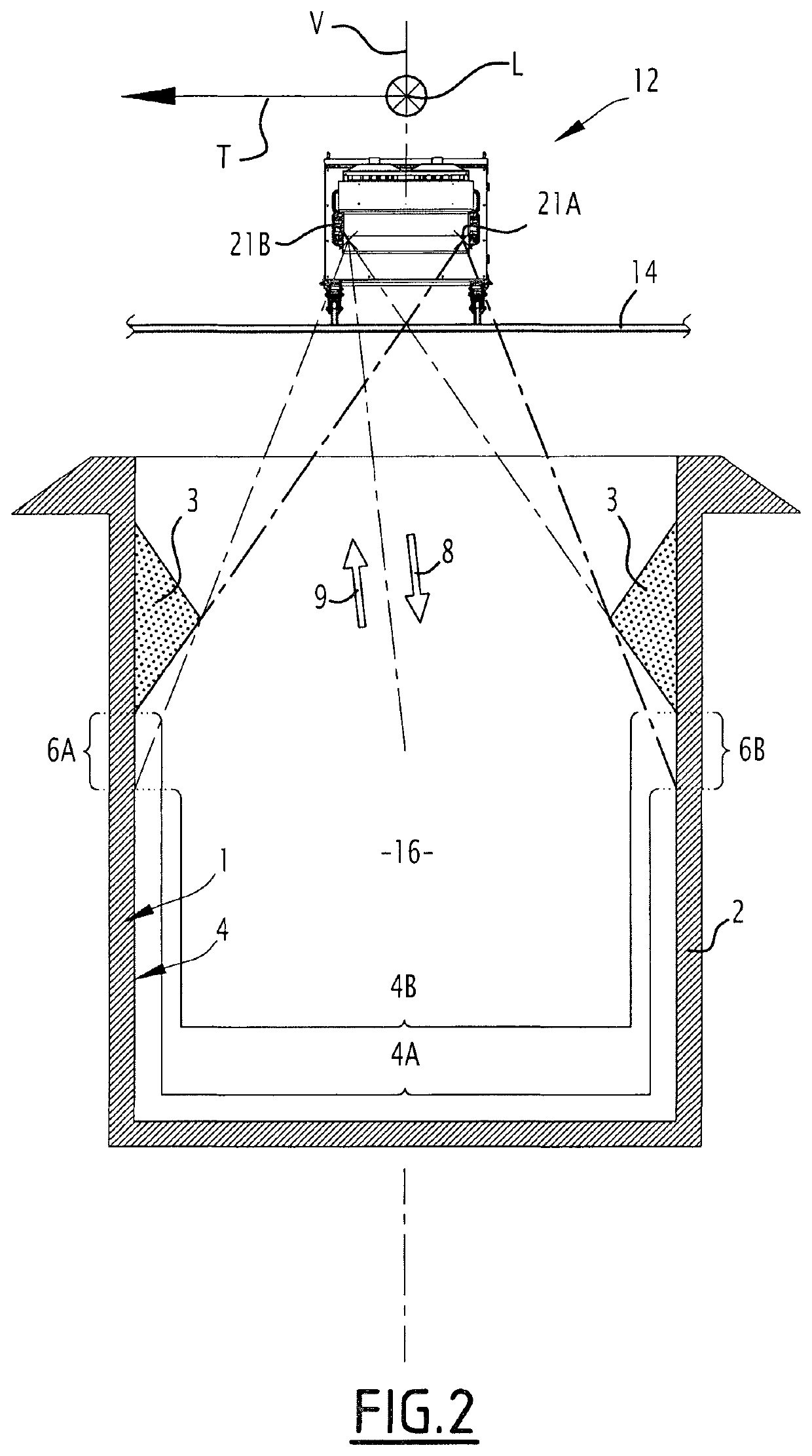
[0066]With reference to FIGS. 1 and 2, an installation 10 according to the invention is described.
[0067]The installation 10 comprises the receptacle 2, a device 12 for measuring wear of the refractory lining, and a floor 14 on which the device stands.
[0068]The receptacle 2 is for example a steel ladle intended to contain molten steel, for example coming from an electric arc furnace. The ladle is approximately symmetrical around a vertical direction V. The ladle defines a volume 16 for receiving molten steel, and for example has the deposit 3 around its mouth.
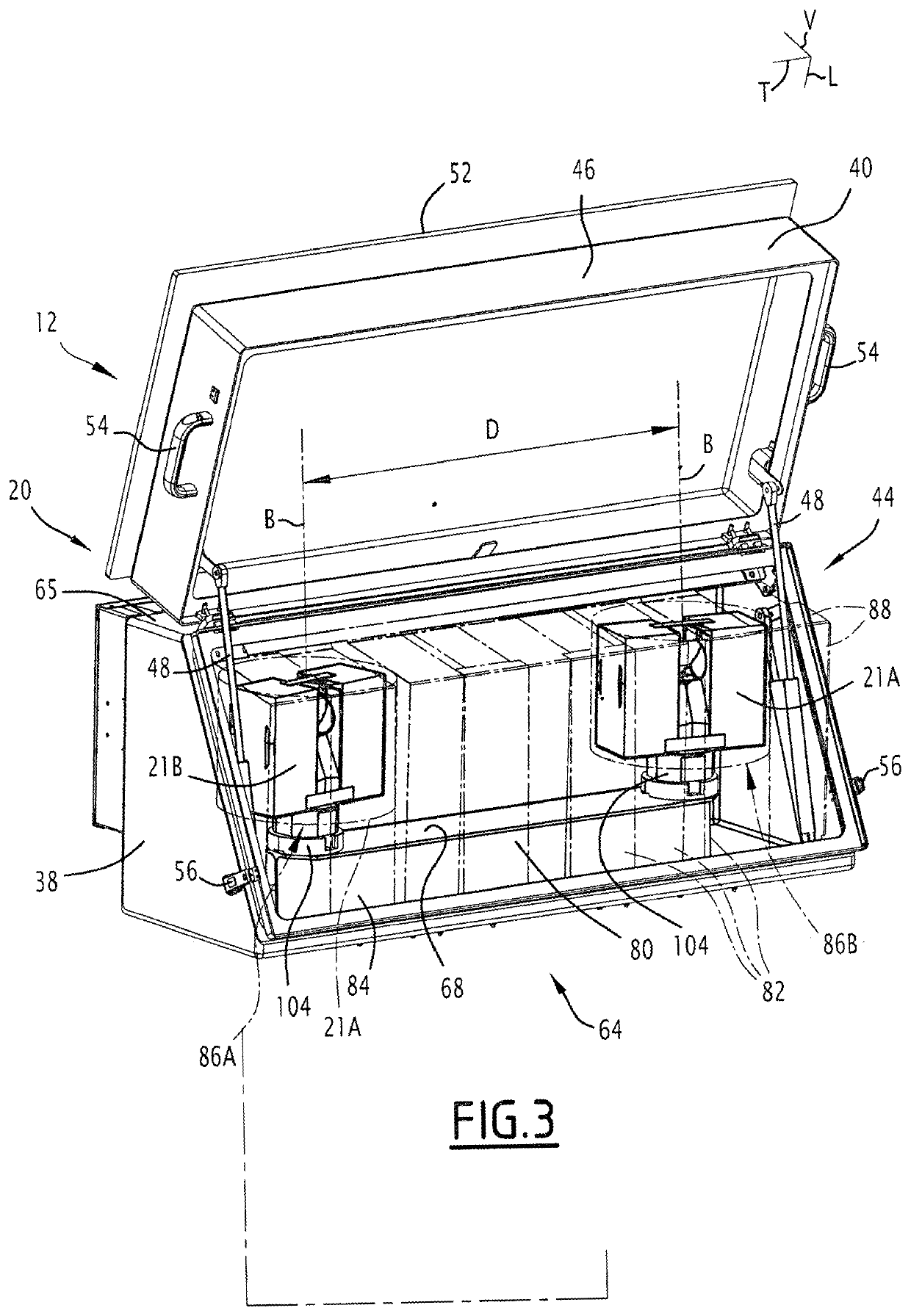
[0069]The device 12 comprises a box 20, the two laser scanners 21A, 21B located within the box, a base 22, and an arm 24 holding the box and protruding from the base along a longitudinal direction L approximately horizontal.
[0070]The box 20 is located above the ladle in this example in this example.
[0071]The base 22 is advantageously adapted to roll on the ground 14.
[0072]The base 22 includes a computer 29, optionally a control ...
second embodiment
[0130]An installation 200 according to the invention will now be described with reference to FIG. 8. The installation 200 is analogous to the installation 100 shown in FIG. 7. Similar elements bear the same numeral references. Only the differences will be described in detail.
[0131]The installation 200 comprises a receptacle 202 which is an electric arc furnace having a refractory lining 201, and a door 203.
[0132]The device 12 is in the same configuration as represented in FIGS. 1 and 2, with the arm 24 extending along the longitudinal direction L (horizontally), so that the box is located inside the furnace.
[0133]The use and the advantages of the installation 200 are similar with those of the installations 10 and 100, with the following differences.
[0134]Prior to use, the device 12 is moved on the floor 14 in order to introduce the box 20 within the receptacle 202 via the door 203. Then scanning is performed in the same way as previously described, with the same results and advantag...
PUM
Abstract
A process for measuring wear of a refractory lining of a receptacle intended to contain molten metal, containing the following steps:scanning a first surface of the refractory lining using a first laserscanner in order to obtain a first initial set of data representative of the first surface,scanning a second surface of the refractory lining using a second laserscanner, distinct from the first laserscanner, in order to obtain a second initial set of data representative of the second surface, wherein the second surface includes a grey zone for the first laser scanner, the receptacle defining an obstacle located between the first laser scanner and the grey zone during scanning by the first laser scanner, andcalculating a final set of data using the first initial set of data and the second initial set of data, the final set of data being representative of a surface of the refractory lining including the first surface and the second surface.
Description
FIELD OF THE INVENTION[0001]The present invention relates to a process for measuring wear of a refractory lining of a receptacle intended to contain molten steel, in particular a ladle, an electric arc furnace (hereafter EAF) or a converter.[0002]The invention also relates to a corresponding installation comprising the receptacle.BACKGROUND[0003]Receptacles such as a ladle and an EAF include a refractory lining acting as a protection against high temperatures when the receptacle contains molten steel. However, the refractory lining is subject to wear or deposits coming from the molten steel.[0004]Controlling the refractory lining plays an important role in order to achieve continuous and safe operation of the receptacle. Performing a visual check of the receptacle, when empty, has been the most common way to control the condition of the refractory lining and how it evolves.[0005]However, this method has proven somewhat difficult, due to the environment of the receptacle in terms of ...
Claims
Application Information
Patent Timeline
Application Date:The date an application was filed.
Publication Date:The date a patent or application was officially published.
First Publication Date:The earliest publication date of a patent with the same application number.
Issue Date:Publication date of the patent grant document.
PCT Entry Date:The Entry date of PCT National Phase.
Estimated Expiry Date:The statutory expiry date of a patent right according to the Patent Law, and it is the longest term of protection that the patent right can achieve without the termination of the patent right due to other reasons(Term extension factor has been taken into account ).
Invalid Date:Actual expiry date is based on effective date or publication date of legal transaction data of invalid patent.

