

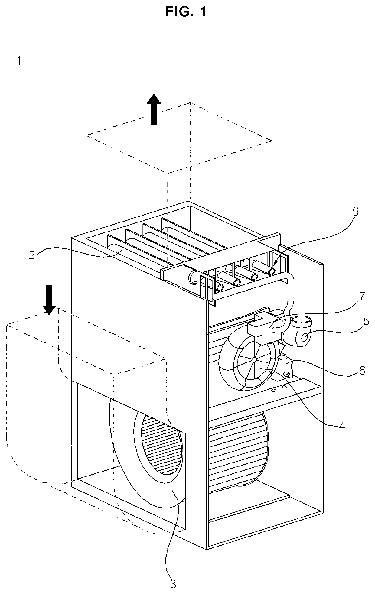
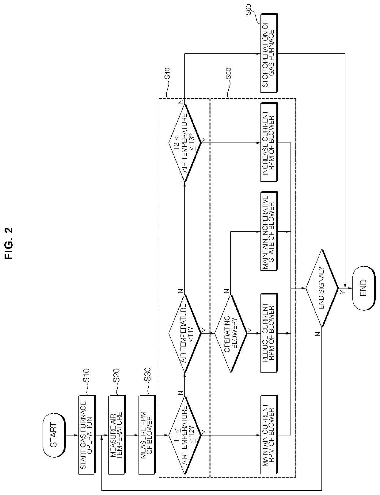
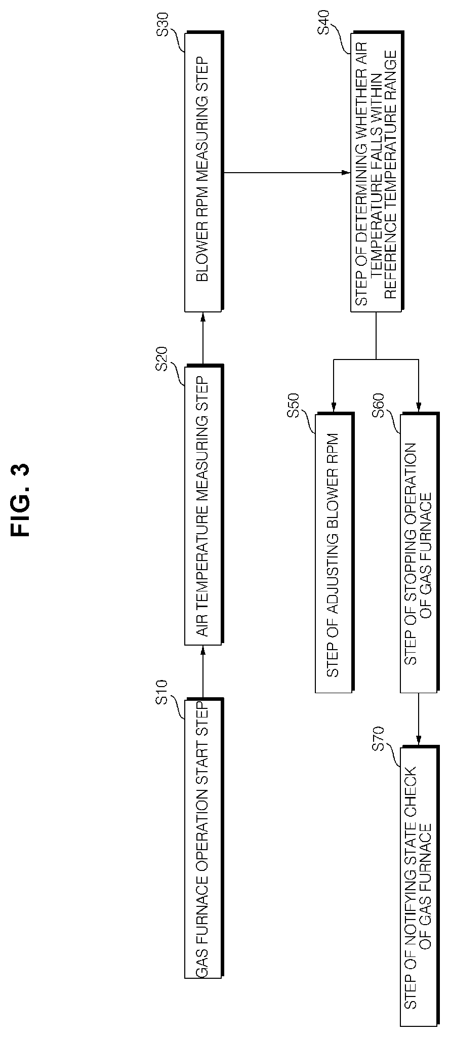
Rpm control method of blower for gas furnace
a technology of rpm control and gas furnace, which is applied in the direction of furnaces, combustion regulation, combustion process, etc., can solve the problems of only preventing air in the outlet side of the gas furnace, the temperature of the air supplied to the room from the gas furnace is too high or low, and the occupant is not comfortable. to feel uncomfortable
- Summary
- Abstract
- Description
- Claims
- Application Information
AI Technical Summary
Benefits of technology
Problems solved by technology
Method used
Image

Examples
Embodiment Construction
[0018]Hereinafter, the embodiments disclosed in the present specification will be described in detail with reference to the accompanying drawings, and the same or similar elements are denoted by the same reference numerals even though they are depicted in different drawings and redundant descriptions thereof will be omitted. In the following description, with respect to constituent elements used in the following description, the suffixes “module” and “unit” are used or combined with each other only in consideration of ease in the preparation of the specification, and do not have or serve as different meanings. Accordingly, the suffixes “module” and “unit” may be interchanged with each other. In addition, the accompanying drawings are provided only for a better understanding of the embodiments disclosed in the present specification and are not intended to limit the technical ideas disclosed in the present specification. Therefore, it should be understood that the accompanying drawing...
PUM
 Abstract
Description
Claims
Application Information