Electronic device, display device, method for manufacturing the same, and system including a plurality of display devices

a technology of electronic devices and display devices, applied in the field of display devices, can solve the problems of reducing the reliability of the display device, easy damage to the surface of the display portion, etc., and achieve the effects of reducing manufacturing costs, increasing total power consumption, and reducing damage to the display portion with a flexible region of the electronic devi

Active Publication Date: 2017-03-30
SEMICON ENERGY LAB CO LTD
View PDF8 Cites 31 Cited by
  • Summary
  • Abstract
  • Description
  • Claims
  • Application Information

AI Technical Summary

Benefits of technology

[0052]Damage to a display portion with a flexible region of an electronic device due to a change in shape that is caused by an external force applied to the electronic device can be reduced.
[0053]It is possible to provide a novel electronic device.
[0054]When a plurality of display panels manufactured using the same photomask are used for one display portion of an electronic device, manufacturing cost can be reduced.
[0055]A management system that controls a plurality of devices, such as display devices including a stationary television and a plurality of lighting devices, placed indoors and manages environments thereof using the cloud is provided. When a user possesses a plurality of display devices, it is hard to avoid an increase in the total power consumption; however, when the plurality of display devices used for different purposes are controlled using the cloud and the power consumption is decentralized, the amount of increase in the power consumption can be reduced.

Problems solved by technology

However, when the plastic film is used for the display device, there is a disadvantage that a surface of a display portion is easy to damage.
In addition, since the plastic film has a low blocking property against moisture or the like, there is another disadvantage that reliability of the display device is decreased as compared with the case where the glass substrate is used.

Method used


Image

  • Electronic device, display device, method for manufacturing the same, and system including a plurality of display devices
  • Electronic device, display device, method for manufacturing the same, and system including a plurality of display devices
  • Electronic device, display device, method for manufacturing the same, and system including a plurality of display devices

Examples


embodiment 1

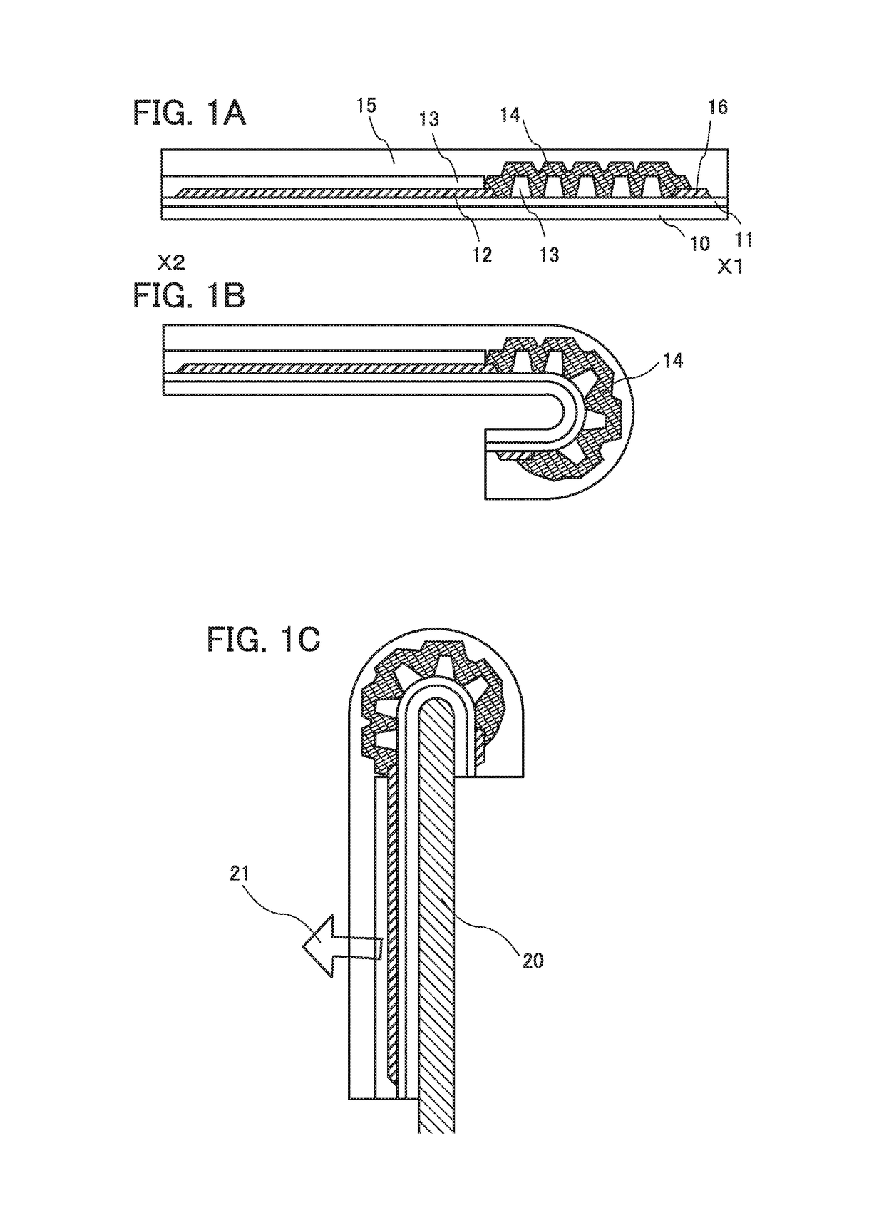
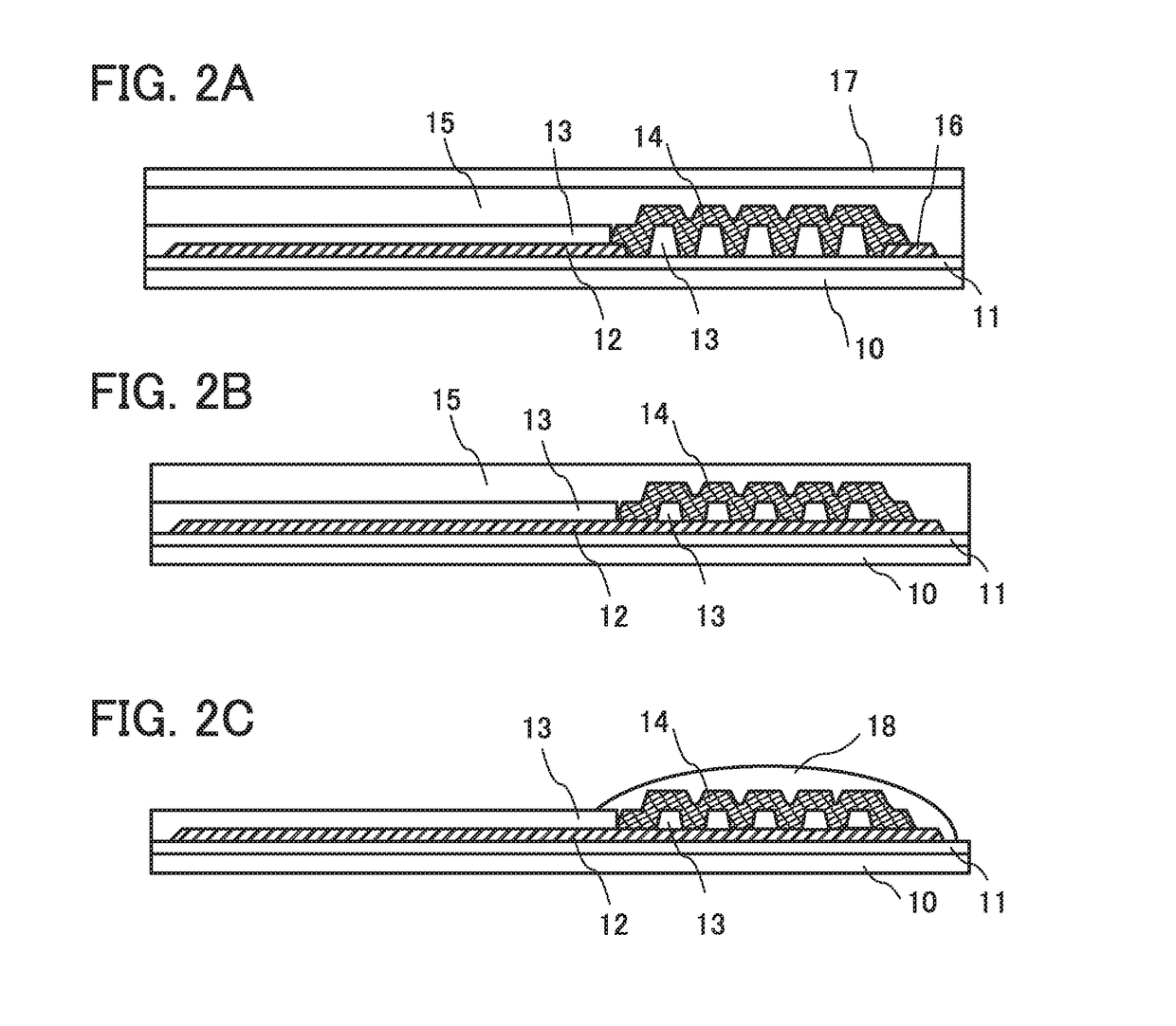
[0074]FIG. 1A illustrates an example of a simplified view of a cross-sectional structure of a display device. Note that an organic EL element that is a display element is not illustrated in FIG. 1A for simplicity. In a conventional structure, an FPC that is connected to a terminal electrode over a film is bent for storage; however, in this embodiment, a film 10 is bent. Accordingly, the structure in this embodiment is effective in the case where a display panel is placed in a housing with a limited storage space.

[0075]The display device illustrated in FIG. 1A includes an insulating layer 11, a wiring 12, an insulating layer 13, a conductive layer 14 including a metal nanoparticle, and a sealing layer 15 over the film 10. A wiring 16 is electrically connected to the wiring 12 through the conductive layer 14 including the metal nanoparticle.

[0076]In a bent portion of the display device, the wiring connection might be partly broken in the case of a sharp bend or repeated bends.

[0077]In...

embodiment 2

[0115]FIGS. 6A to 6C illustrate an example in which a chair as an example of furniture is provided with a display portion. In the display portion, one display panel 160 or the plurality of display panels 160a to 160c described in Embodiment 1 is used.

[0116]FIG. 6A illustrates an example of a perspective view of the chair. The chair includes leg portions 61, a seating portion 62, and a backrest portion 63. The backrest portion includes a display device 64. FIG. 6B illustrates a cross-sectional view of the chair.

[0117]The display device 64 is placed on the backrest portion 63 of the chair.

[0118]In the case where one display panel 160 is used for the display device 64, a portion corresponding to an uppermost part of the backrest portion does not display an image. The structure body 20 illustrated in FIG. 1C corresponds to the backrest portion 63 and FIG. 1C corresponds to a cross-sectional view of the display device 64.

[0119]In the case where the plurality of display panels 160a to 160...

embodiment 3

[0143]In this embodiment, an example in which the display panel described in Embodiment 1 is provided in part of an interior of a vehicle is described.

[0144]FIG. 8A is an external view of an automobile 9700. FIG. 8B illustrates a driver's seat of the automobile 9700. The automobile 9700 includes a car body 9701, wheels 9702, a dashboard 9703, lights 9704, and the like. The display device of one embodiment of the present invention can be used in a display portion or the like of the automobile 9700. For example, the display device of one embodiment of the present invention can be provided in display portions 9710 to 9715 illustrated in FIG. 8B.

[0145]The display portion 9710 is a display device provided in an automobile windshield. In the display portion 9710, a plurality of display panels are aligned and used as one display device. The display portion 9710 can also be used as lighting in the car.

[0146]The display portion 9711 is a display device provided on a backrest portion of a sea...


PUM


Abstract

A power saving system using a plurality of flexible display devices placed on various places is provided. A structure of a bendable portion in a display device is improved. Specifically, a wiring partly including a metal nanoparticle is used. Openings are formed in an insulating layer so that the wiring becomes substantially longer by meandering in cross section. When a plurality of openings are formed and aligned, a portion that is easy to bend is formed along the line where they are aligned. A plurality of display panels are used for one display portion. The flexible display portion can be provided on a surface, specifically, a curved surface of furniture such as a chair or a sofa.

Description

BACKGROUND OF THE INVENTION[0001]1. Field of the Invention[0002]The present invention relates to a display device, a manufacturing method thereof, and an indoor environment management system using the display device.[0003]Note that one embodiment of the present invention is not limited to the above technical field. The technical field of one embodiment of the invention disclosed in this specification and the like relates to an object, a method, a manufacturing method, or a system. Furthermore, one embodiment of the present invention relates to a process, a machine, manufacture, or a composition of matter. Specifically, examples of the technical field of one embodiment of the present invention disclosed in this specification include a semiconductor device, a display device, a liquid crystal display device, a light-emitting device, a lighting device, a power storage device, a memory device, an imaging device, a method for operating any of them, a method for manufacturing any of them, ...

Claims


Application Information

Patent Timeline
Patent Type & Authority Applications(United States)
IPC IPC(8): G09G5/12G09G3/3208H01L51/00H01L27/32H01L51/52G06F3/14H05B37/02
CPCG09G5/12G06F3/1423G09G3/3208H05B37/0209G09G2380/02H01L51/5253H01L51/0097G09G2320/043G09G2360/144H01L27/3276Y02E10/549H10K59/131H10K77/111H10K50/844
Inventor KUWABARA, HIDEAKI
Owner SEMICON ENERGY LAB CO LTD
Why Eureka
Try Eureka