Information processing system and method of confirming operation history
- Summary
- Abstract
- Description
- Claims
- Application Information
AI Technical Summary
Benefits of technology
Problems solved by technology
Method used
Image

Examples
first embodiment
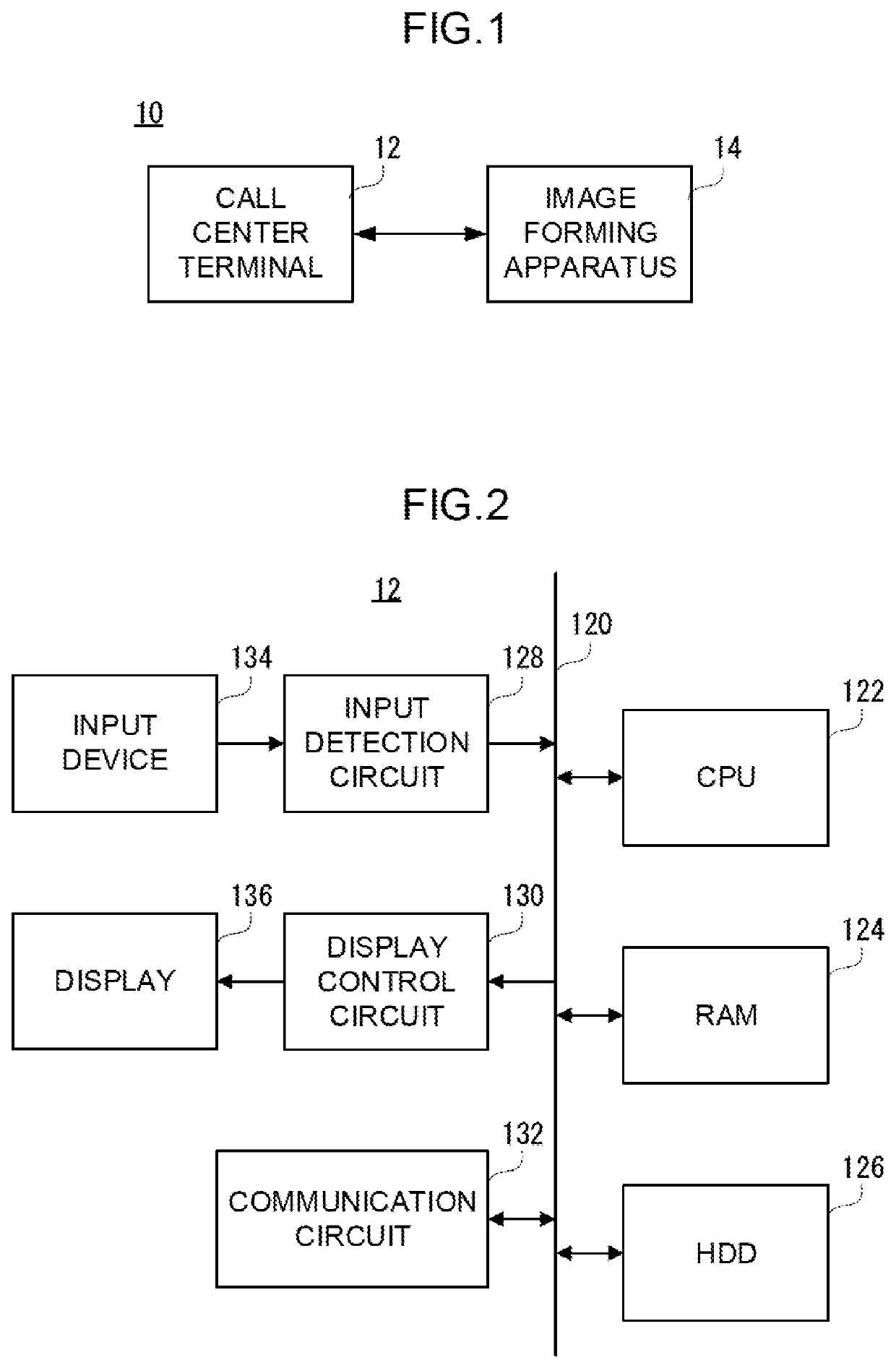
[0031]FIG. 1 is a diagram showing one example of the structure of an information processing system 10 of the present invention. Referring to FIG. 1, the information processing system 10 corresponding to a first embodiment of the present invention includes a call center terminal 12 and an image forming apparatus 14. The call center terminal 12 and the image forming apparatus 14 are communicably connected to each other via a network such as the Internet and a LAN.
[0032]Although FIG. 1 shows one image forming apparatus 14, the number of image forming apparatuses 14 may be two or more.
[0033]The call center terminal 12 is a general-purpose computer (terminal) used by an operator of a call center. Specifically, the call center terminal 12 corresponds to a desktop PC, a notebook (laptop) PC, a tablet PC, and the like.
[0034]FIG. 2 is a block diagram showing the electrical configuration of the call center terminal 12 shown in FIG. 1. Referring to FIG. 2, the call center terminal 12 includes ...
second embodiment
[0112]An information processing system 10 of a second embodiment has the same structure as that of the first embodiment except that identification information of an image forming apparatus 14 is transmitted to a call center terminal 12 when a predetermined instruction is received by the image forming apparatus 14. Therefore, only the parts different from the first embodiment will be explained, and redundant explanation will not be provided.
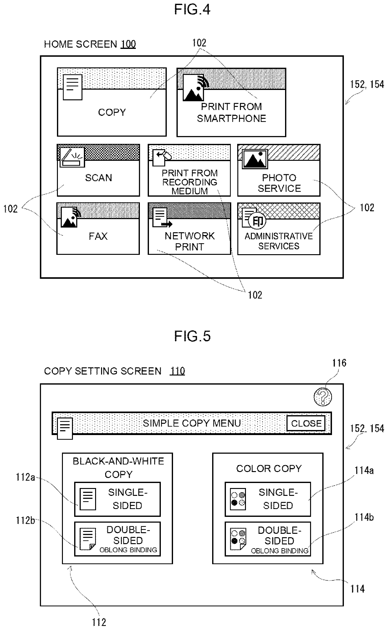
[0113]FIG. 10 is an explanatory diagram showing one example of a copy setting screen 110 of the second embodiment. When a help icon 116 is touched on each of operation screens including the copy setting screen 110, a function selection window 118 is displayed as shown in FIG. 10. Here, a case where the help icon 116 is touched on the copy setting screen 110 will be described as an example. The function selection window 118 is displayed at a central part of a display area of a display 154 to overlap a front surface of the copy setting screen 110. T...
third embodiment
[0124]An information processing system 10 of a third embodiment has the same structure as that of the first embodiment except that operation history image data is stored in a server 16. Therefore, only the parts different from the first embodiment will be explained, and redundant explanation will not be provided.
[0125]FIG. 12 is a diagram showing one example of the structure of the information processing system 10 of the third embodiment. As shown in FIG. 12, the information processing system 10 of the third embodiment includes the server 16, and the server 16 is communicably connected to a call center terminal 12 and an image forming apparatus 14 via a network.
[0126]The server 16 is a general-purpose server, and includes components such as a CPU, RAM, and a communication module. In addition, the server 16 includes a storage configured by non-volatile memories such as an HDD, an SSD, a flash memory, and an EEPROM. Note that the server 16 may be a cloud server.
[0127]In the informatio...
PUM
 Abstract
Description
Claims
Application Information
 - R&D
- Intellectual Property
- Life Sciences
- Materials
- Tech Scout
- Unparalleled Data Quality
- Higher Quality Content
- 60% Fewer Hallucinations
Browse by: Latest US Patents, China's latest patents, Technical Efficacy Thesaurus, Application Domain, Technology Topic, Popular Technical Reports.
© 2025 PatSnap. All rights reserved.Legal|Privacy policy|Modern Slavery Act Transparency Statement|Sitemap|About US| Contact US: help@patsnap.com