Supercharge Your Innovation With Domain-Expert AI Agents!

Image processing apparatus, image processing method, and storage medium

a technology of image processing apparatus and image processing method, applied in the field of generating an hdr image, can solve the problem that the combined image may have a difference in noise characteristic between the light portion and the dark portion, and achieve the effect of reducing the noise gap and reducing the noise characteristi

Active Publication Date: 2020-03-05
CANON KK
View PDF0 Cites 0 Cited by
  • Summary
  • Abstract
  • Description
  • Claims
  • Application Information

AI Technical Summary

Benefits of technology

The patent aims to address the issue of noise gap that appears at the boundary between light and dark portions in HDR composition of images captured in a time-division manner. The technique is designed to reduce the noise gap and improve the quality of the HDR image.

Problems solved by technology

However, with the method disclosed in Japanese Patent Laid-Open No. 2015-50733, the combined image may possibly have a difference in noise characteristic between a light portion and the dark portion as compared to the captured image, since the image of the dark portion to be combined is captured with intermediate exposure between the exposure for the captured image and the adequate exposure.

Method used


Image

  • Image processing apparatus, image processing method, and storage medium
  • Image processing apparatus, image processing method, and storage medium
  • Image processing apparatus, image processing method, and storage medium

Examples


first embodiment

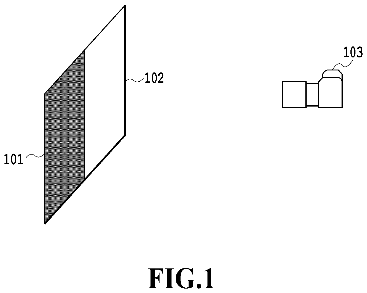
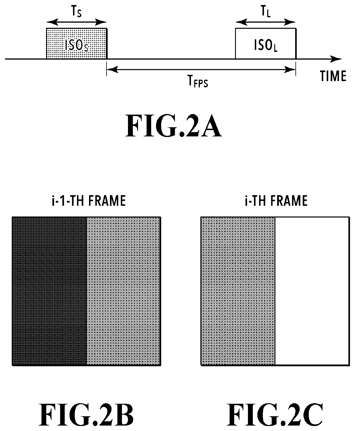
[0029]In the present embodiment, a case will be exemplarily discussed in which, as shown in FIG. 1, temporally divided images of an object at rest with a wide dynamic range having a dark portion 101 and a light portion 102 are captured by continuous image capturing under different exposure conditions (different sensor sensitivities in the present embodiment) with an image capturing apparatus 103. FIGS. 2A to 2C are diagrams for explaining time-division image capturing and time-division images obtained by the time-division image capturing. FIG. 2A shows a time line indicating the exposure start and end timings for frame images obtained by the time-division image capturing. The i−1-th frame image (hereinafter described as the frame image i−1) is captured with a low sensor sensitivity (also referred to as ISO sensitivity) ISOs and an exposure time TS. On the other hand, the i-th frame image (hereinafter described as the frame image i) is captured with a sensor sensitivity ISOL higher t...

second embodiment

[0053]In the first embodiment, a description has been given of a method in which captured images and an HDR image are divided into regions, and the noise gap amount is derived from the difference in standard deviation between the divided regions. However, in a case where there is shadow-detail loss in a divided region corresponding to a dark portion, a histogram of the pixel values of the divided region corresponding to the dark portion is not a normal distribution, as shown in FIG. 16. This may possibly lower the accuracy of derivation of the noise gap amount. In the present embodiment, a description will be given of a method of accurately deriving the noise gap amount even in the case where there is shadow-detail loss in the divided region corresponding to the dark portion.

[0054]FIG. 17 is a flowchart showing a noise gap amount derivation process in the second embodiment. Note that the processes in S1701, S1702, and S1704 to S1710 in FIG. 17 are similar to the processes in S901, S...


PUM


Abstract

An object of the technique of the present disclosure is to reduce the noise gap that appears at the boundary between light and dark portions in HDR composition of images captured in a time-division manner. The technique of the present disclosure comprises: an obtaining unit configured to obtain a plurality of captured images of an object captured under exposure conditions having different SN ratio characteristics; a combining unit configured to generate a high-dynamic range image by combining the plurality of captured images; a division unit configured to divide the generated high-dynamic range image into a plurality of regions; a derivation unit configured to derive a noise gap amount representing the difference in noise amount between the divided regions obtained by the division; and an updating unit configured to update at least one of the exposure conditions on the basis of the noise gap amount.

Description

BACKGROUND OF THE INVENTIONField of the Invention[0001]The technique of the present disclosure relates to a technique for generating an HDR image.Description of the Related Art[0002]In high-dynamic range (HDR) composition of images captured repetitively in a time-division manner with different sensor sensitivities, the difference in sensor sensitivity and exposure correction in the composition sometimes result in a difference in noise characteristic between a light portion and a dark portion in the HDR image, so that a noise gap appears at the boundary between the light and dark portions. Heretofore, various methods to reduce deterioration in image quality of light and dark portions have been proposed. Japanese Patent Laid-Open No. 2015-50733 discloses a method including detecting a dark portion from a captured image, setting the exposure such that the average luminance of the dark portion region can be an intermediate value between the exposure for the captured image and adequate e...

Claims


Application Information

Patent Timeline
IPC IPC(8): H04N5/235
CPCH04N5/2352H04N5/2355H04N25/63H04N23/72H04N23/741H04N25/60
Inventor TASHIRO, HIDEYASU
Owner CANON KK
Features
  • R&D
  • Intellectual Property
  • Life Sciences
  • Materials
  • Tech Scout
  • Unparalleled Data Quality
  • Higher Quality Content
  • 60% Fewer Hallucinations
Learn More