Fasteners and system for providing fasteners in bone

a technology of fasteners and bone, applied in the direction of fasteners, internal osteosynthesis, osteosynthesis devices, etc., can solve the problems of difficult to obtain proper screw fixation within the pedicle, difficult to obtain proper screw fixation, and often problematic screw use in fixing or fixing the pedicle of the vertebrae, etc., to achieve complete precision

Inactive Publication Date: 2020-04-02
LIPOW KENNETH I
View PDF5 Cites 7 Cited by
  • Summary
  • Abstract
  • Description
  • Claims
  • Application Information

AI Technical Summary

Problems solved by technology

However, the use of screws in repairing or fixation into the vertebrae pedicle is often problematic due to variations and differences from one pedicle to the next.
These differences may include differences in pedicle shapes, sizes, and pedicle anatomy that make it difficult to obtain proper screw fixation within the pedicle.
This angle degree variation often makes it difficult to obtain proper screw fixation as the varying angles result in different stresses being applied to the pedicles.
Irregularities in the pedicle internal architecture also adversely affect screw fixation, as well as these irregularities disturbing navigational trajectories, particularly within computerized procedures that require manual.
Still another problem with use of bolts and screws in pedicle surgery is that often the bolts and screws do not sufficiently go into or fixate within the pedicle dense bone.
However, computer guided surgical systems are limited as they require manual surgical execution.
This leads to the potential of human error, incorrect or incomplete screw insertions, extended surgical times and costs.
The computer aided or guided surgical systems are also subject to human and operating room limitations, as the surgeon may need to react to events occurring during a surgical procedure or within the operating room that may increase occurrence of error.

Method used


Image

  • Fasteners and system for providing fasteners in bone
  • Fasteners and system for providing fasteners in bone
  • Fasteners and system for providing fasteners in bone

Examples


Embodiment Construction

)

[0031]In describing the preferred embodiment of the present invention, reference will be made herein to FIGS. 1-14 of the attached drawings, as well as the drawings detailed herein below.

[0032]The various embodiments of the invention overcome problems of known computer systems, medical equipment and surgical hardware, particularly in connection with surgical procedures involving dense bone, such as, pedicle dense bone. In one or more embodiments the invention is directed to improved medical equipment, medical procedures, and medical systems that provide accurate results, and decreased operation times and costs.

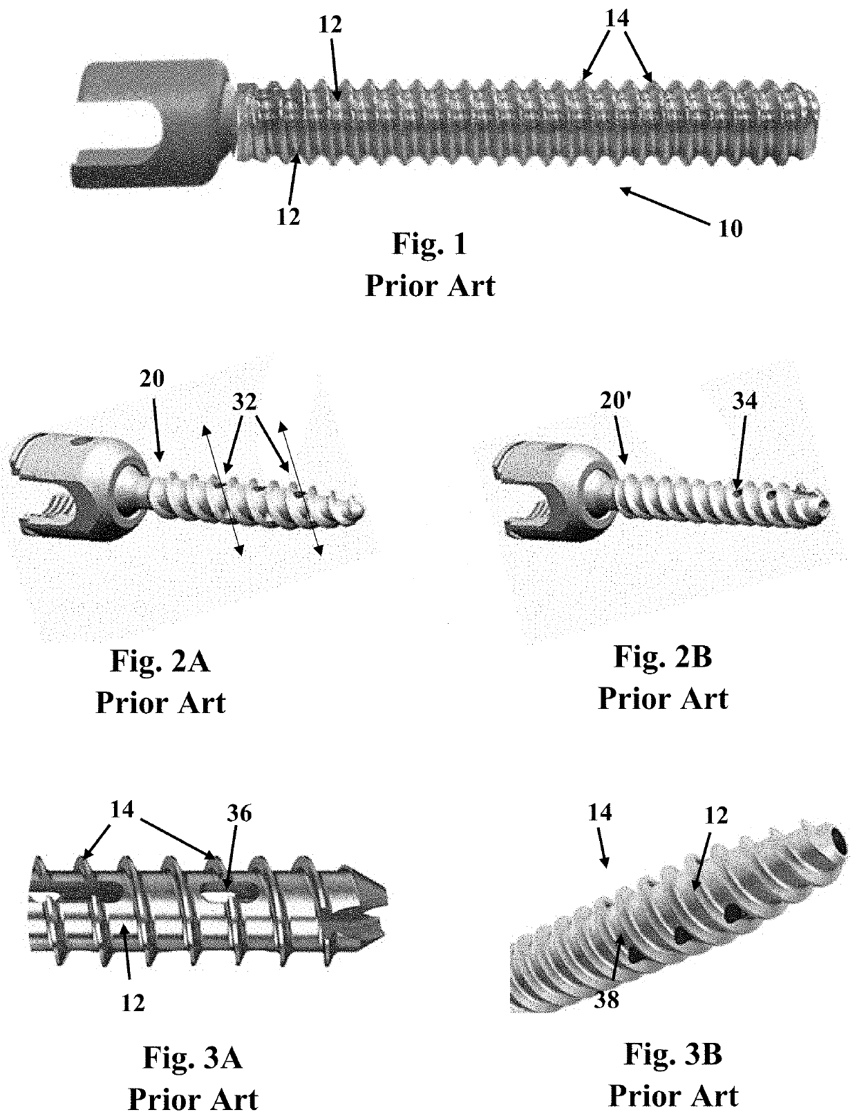
[0033]In one or more embodiments the invention is directed to improved fenestrated fasteners, and in particular, improved fenestrated bolts and screws. Referring to FIGS. 1A to 3B, medical grade bolts and screws having passive fenestrations (i.e., openings) have been used over the years in surgical procedures. The fenestrations may be provided in a bolt 10 or they may be prov...


PUM


Abstract

Fastening devices for bone reconstruction that include a head portion; a centrally located rod having a length, a first end and a second end, the rod extending from the head portion at the first end of the rod; a plurality of threads extending around the centrally located rod; and a plurality of angled fenestrae residing within one or more of the plurality of threads to provide an angled fenestrated fastener for bone reconstruction. Computerized surgical systems, methods and equipment for fully-robotically implanting the angled fenestrated fasteners of the invention into a predetermined (i.e., premapped) bone with complete precision.

Description

[0001]The present invention claims priority from U.S. Provisional Patent Application Ser. No. 62 / 740,059, the contents of which are incorporated herein in their entirety by reference thereto.BACKGROUND OF THE INVENTION1. Field of the Invention[0002]The present invention relates to bone and joint repair, and in particular, to fasteners, computerized mapping and navigational systems and equipment for implanting fasteners into a bone or joint.2. Description of Related Art[0003]The spine is a series of vertebrae extending from the skull to the small of the back. The spine encloses the spinal cord and provides support for the thorax and abdomen. There are four main regions of the spine which include the cervical spine, thoracic spine, lumbar spine, and sacral region.[0004]The cervical spine relates to the region of the neck. The thoracic spine includes 12 vertebrae that provide stability and structural support to the upper back, as well as being attached to the rib cage to protect vital ...

Claims


Application Information

Patent Timeline
Patent Type & Authority Applications(United States)
IPC IPC(8): A61B17/86A61B17/70A61B34/32
CPCA61B17/7005A61B17/864A61B34/32A61B2017/681A61B17/8605A61B34/30A61B17/7032A61B17/7098
Inventor LIPOW, KENNETH I.
Owner LIPOW KENNETH I
Why Eureka
Try Eureka