Vehicle body rear structure

Active Publication Date: 2020-04-02
HONDA MOTOR CO LTD
View PDF0 Cites 5 Cited by
  • Summary
  • Abstract
  • Description
  • Claims
  • Application Information

AI Technical Summary

Benefits of technology

The present invention provides a vehicle body rear structure that prevents a small load in a rear collision from being transmitted easily to the rear subframe. This is achieved by positioning shock-absorbing structures in front of the rear subframe and allowing the load to be absorbed by them. This prevents deformation of the rear subframe and ensures proper load distribution. Additionally, the invention ensures that the load does not act on the driving source by positioning shock-absorbing structures more rearward. Overall, this helps to enhance safety and prevent accidents.

Problems solved by technology

However, in the prior art structure, a load caused in a relatively light rear collision is transmitted to the rear subframe supporting the wheels and the driving source, and the load transmitted to the rear subframe may cause deformation of the rear subframe.
If the rear subframe deforms, it becomes difficult to continue to use the vehicle and a high repair cost may become necessary.

Method used


Image

  • Vehicle body rear structure
  • Vehicle body rear structure
  • Vehicle body rear structure

Examples


Embodiment Construction

)

[0035]In the following, a vehicle body structure according to an embodiment of the present invention will be described. In the following description, the fore-and-aft direction, the lateral direction (vehicle widthwise direction), and the vertical direction are defined with respect to the vehicle. “Laterally inward (vehicle widthwise inner side)” indicates a direction toward the center of the vehicle in the lateral direction, and “laterally outward (vehicle widthwise outer side)” indicates a direction away from the center of the vehicle in the lateral direction. The frames, panels, and other members constituting the vehicle body structure are made of steel unless otherwise mentioned.

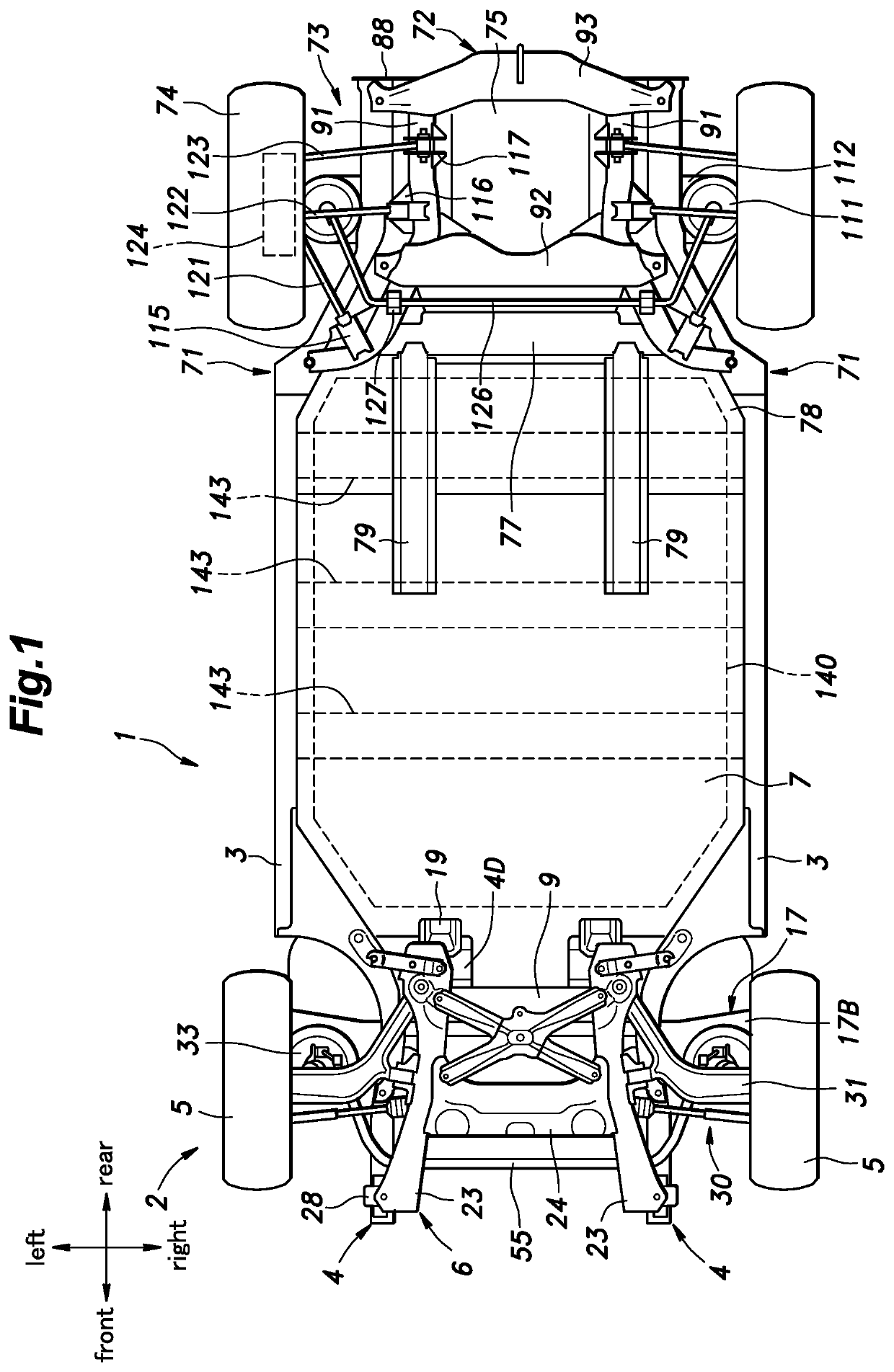
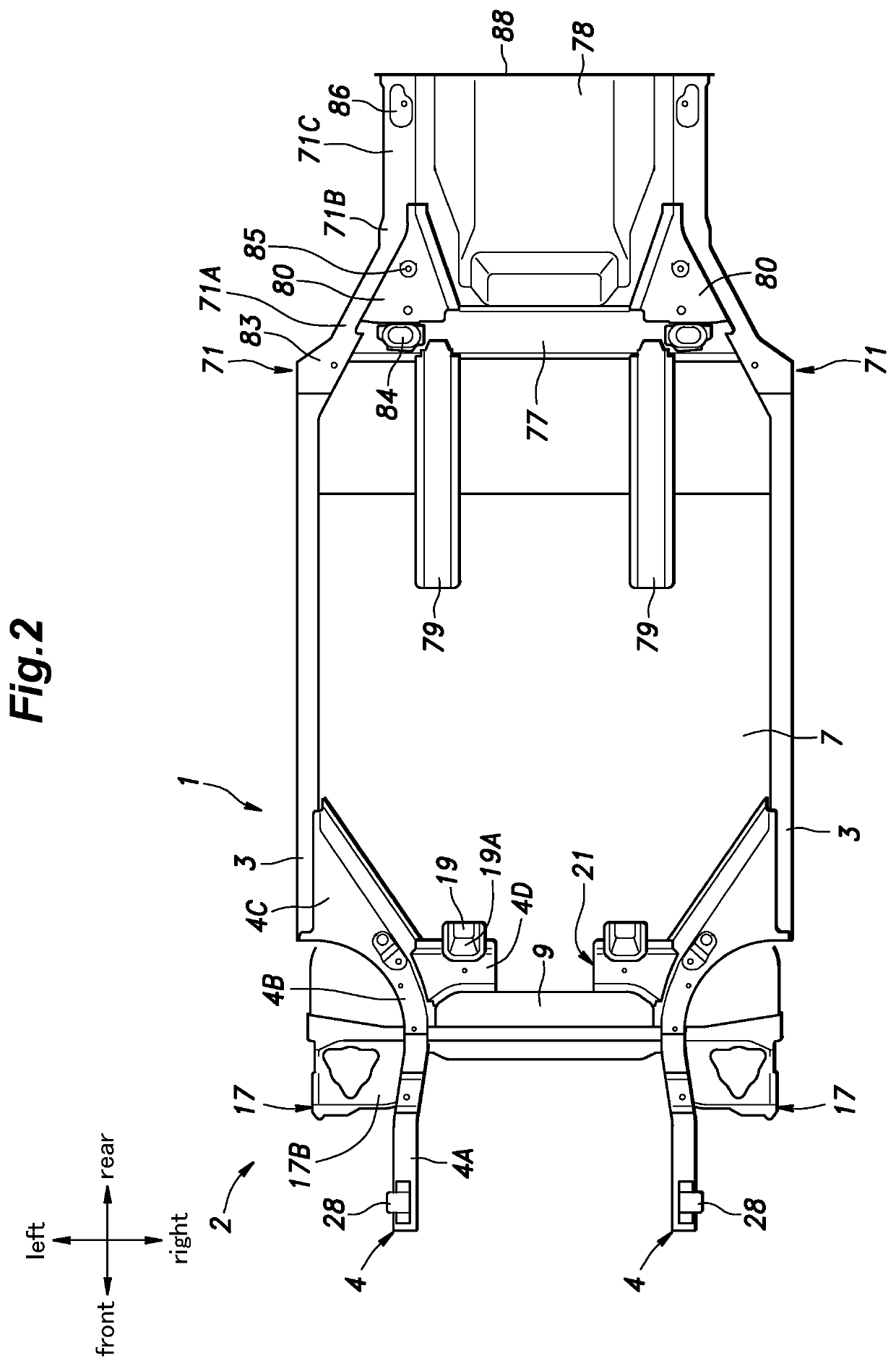
[0036]As shown in FIGS. 1 and 2, the vehicle body structure 1 includes a pair of left and right side sills 3 extending in the fore-and-aft direction on either lateral side of a lower part of the vehicle 2, a pair of left and right front side frames 4 extending in the fore-and-aft direction in a front pa...


PUM


Abstract

A vehicle body rear structure includes: a pair of left and right rear side frames extending in a fore-and-aft direction in a rear part of a vehicle; a rear subframe attached to the rear side frames; and a pair of left and right shock-absorbing structures respectively provided at rear ends of the rear side frames and extending rearward. The rear subframe includes a pair of left and right rear subframe longitudinal members extending in the fore-and-aft direction and a rear subframe cross member extending laterally and joined to the left and right rear subframe longitudinal members. The rear subframe cross member includes a protrusion that protrudes rearward in a laterally central part thereof. A rear end of the protrusion is positioned more rearward than the rear ends of the rear side frames and more forward than rear ends of the shock-absorbing structures.

Description

TECHNICAL FIELD[0001]The present invention relates to a vehicle body rear structure including a rear subframe.BACKGROUND ART[0002]As a vehicle body rear structure of a four-wheel vehicle, there is known a structure including a pair of left and right rear side frames extending in the fore-and-aft direction and a rear subframe attached to the underside of the rear side frames (see JP2011-143871A, for example). The rear subframe supports an engine and a power generator and has a function of dispersing or absorbing the collision load at the time of a rear collision of the vehicle.[0003]However, in the prior art structure, a load caused in a relatively light rear collision is transmitted to the rear subframe supporting the wheels and the driving source, and the load transmitted to the rear subframe may cause deformation of the rear subframe. If the rear subframe deforms, it becomes difficult to continue to use the vehicle and a high repair cost may become necessary. Therefore, it is desi...

Claims


Application Information

Patent Timeline
IPC IPC(8): B60R19/34B62D21/03B62D25/08
CPCB62D21/03B60R19/34B62D25/08B62D21/02B62D21/152B62D21/09B62D21/11B62D21/155
Inventor SAKAI, KAZUHIROHIRAKAWA, TADASHIYAMADA, TAKASHINOGUCHI, SATORUKATO, SEIICHIKANEKO, KANJI
Owner HONDA MOTOR CO LTD
Why Eureka
Try Eureka