Unlock instant, AI-driven research and patent intelligence for your innovation.

Image reading device, image forming apparatus, and image reading method

a technology of image reading and forming apparatus, which is applied in the direction of electrical equipment, pictoral communication, etc., can solve the problems of increasing the size of the reference line holding the member and the increase in the cost of obtaining the level of scale accuracy

Active Publication Date: 2020-04-02
RICOH KK
View PDF0 Cites 4 Cited by
  • Summary
  • Abstract
  • Description
  • Claims
  • Application Information

AI Technical Summary

Benefits of technology

This patent describes an improved image reading device that uses position reference members and circuitry to correct the relative positions of pixels in a reader. The position reference members move in the same direction as the reader and are arranged in a perpendicular direction to the reader. The device includes one or more first position reference members for correcting the relative positions of the reader and a plurality of second position reference members for correcting the relative positions of the pixels. The device reads the reference members and calculates a correction value for each position, switching between the first and second reference members to obtain accurate correction. This technology is particularly useful in image forming apparatuses.

Problems solved by technology

According to a typical image position correcting method, however, an increase in the reading range results in an increase in size of a member holding the reference line and thus an increase in cost for obtaining a level of scale accuracy similar to that obtained by a small-sized member.

Method used


Image

  • Image reading device, image forming apparatus, and image reading method
  • Image reading device, image forming apparatus, and image reading method
  • Image reading device, image forming apparatus, and image reading method

Examples


first embodiment

[0037]the present invention will be described.

[0038]A description will first be given of a hardware configuration of a printing system of the first embodiment.

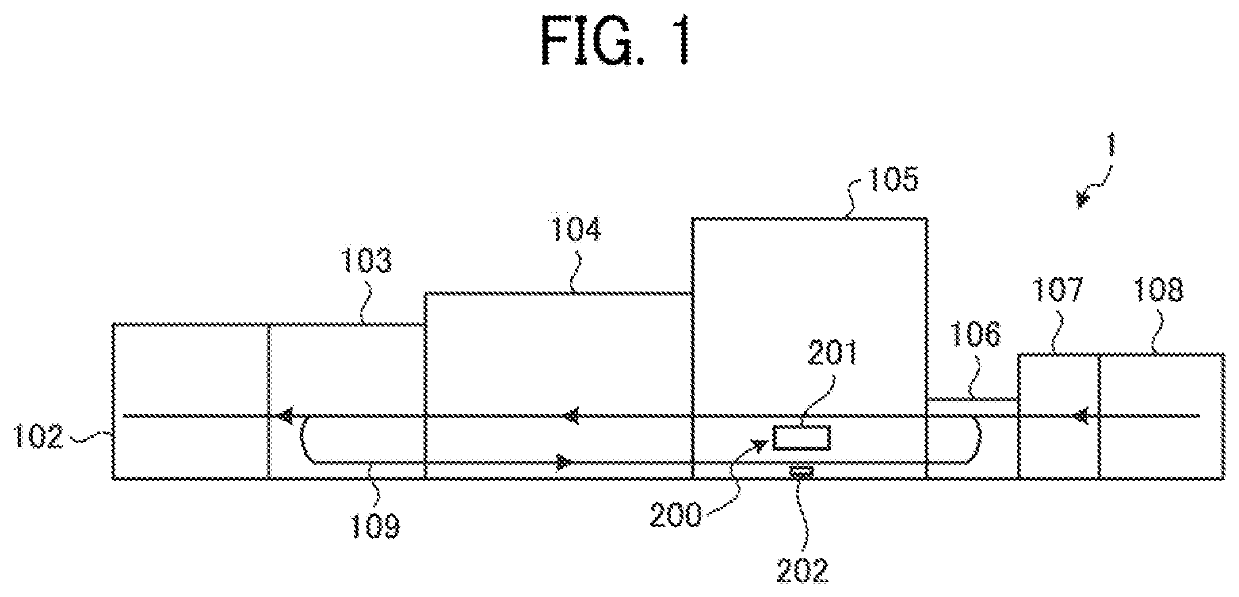
[0039]FIG. 1 is a schematic diagram illustrating an exemplary configuration of a printing system 1 according to the first embodiment. As illustrated in FIG. 1, the printing system 1 is an image forming apparatus including a sheet ejecting device 102, a cooling device 103, a drying device 104, an image forming device 105, a registration device 106, a primer application device 107, and a sheet feeding device 108.

[0040]The sheet feeding device 108 stores a recording medium, which is an object to be processed (i.e., transported). The sheet feeding device 108 supplies the recording medium to a downstream device such as the image forming device 105. The recording medium is a recording sheet (i.e., transfer sheet), for example, but is not limited thereto. The recording medium may be any type of medium on which an image is recordable,...


PUM


Abstract

An image reading device includes reading devices arranged in a main scanning direction perpendicular to a sub-scanning direction, position reference members each including a reference pattern for correcting relative positions of pixels in each of the reading devices or relative positions of the reading devices, and circuitry. The reference members move in the sub-scanning direction relative to the reading devices, and include first reference members for correcting the relative positions of the reading devices and second reference members for correcting the relative positions of the pixels in each of the reading devices. While switching between the first reference members and the second reference members, the circuitry calculates a correction value for a deviation of the pixels in each of the reading devices and a correction value for a deviation of the reading devices based on a result of reading of the reference members.

Description

CROSS-REFERENCE TO RELATED APPLICATION[0001]This patent application is based on and claims priority pursuant to 35 U.S.C. § 119(a) to Japanese Patent Application No. 2018-185853 filed on Sep. 28, 2018 in the Japan Patent Office, the entire disclosure of which is hereby incorporated by reference herein.BACKGROUNDTechnical Field[0002]The present invention relates to an image reading device, an image forming apparatus, and an image reading method.Description of the Related Art[0003]In a reading device formed with an array of a plurality of photoelectric conversion elements, the photoelectric conversion elements may be deviated in position owing to variation in position of the photoelectric conversion elements in the array or torsion or distortion of the reading device occurring in the installation of the reading device.[0004]According to an existing technique, the image of a reference line is read to detect the deviation in position of the reading device and correct the position of the...

Claims


Application Information

Patent Timeline
Patent Type & Authority Applications(United States)
IPC IPC(8): H04N1/00
CPCH04N1/00816H04N1/00809H04N1/00811H04N1/02481H04N1/0249H04N1/02409
Inventor HIRANO, NOBORUSHIBATA, TAKAYUKIISHII, TATSUYA
Owner RICOH KK