Display method, display device, and computer-readable recording medium
a display device and recording medium technology, applied in the field of display methods, can solve the problems of inability to achieve further improvement and unfavorable use by users, and achieve the effect of ensuring the properties of bird's eye view and minuteness without burdensome operation on users
- Summary
- Abstract
- Description
- Claims
- Application Information
AI Technical Summary
Benefits of technology
Problems solved by technology
Method used
Image

Examples
first embodiment
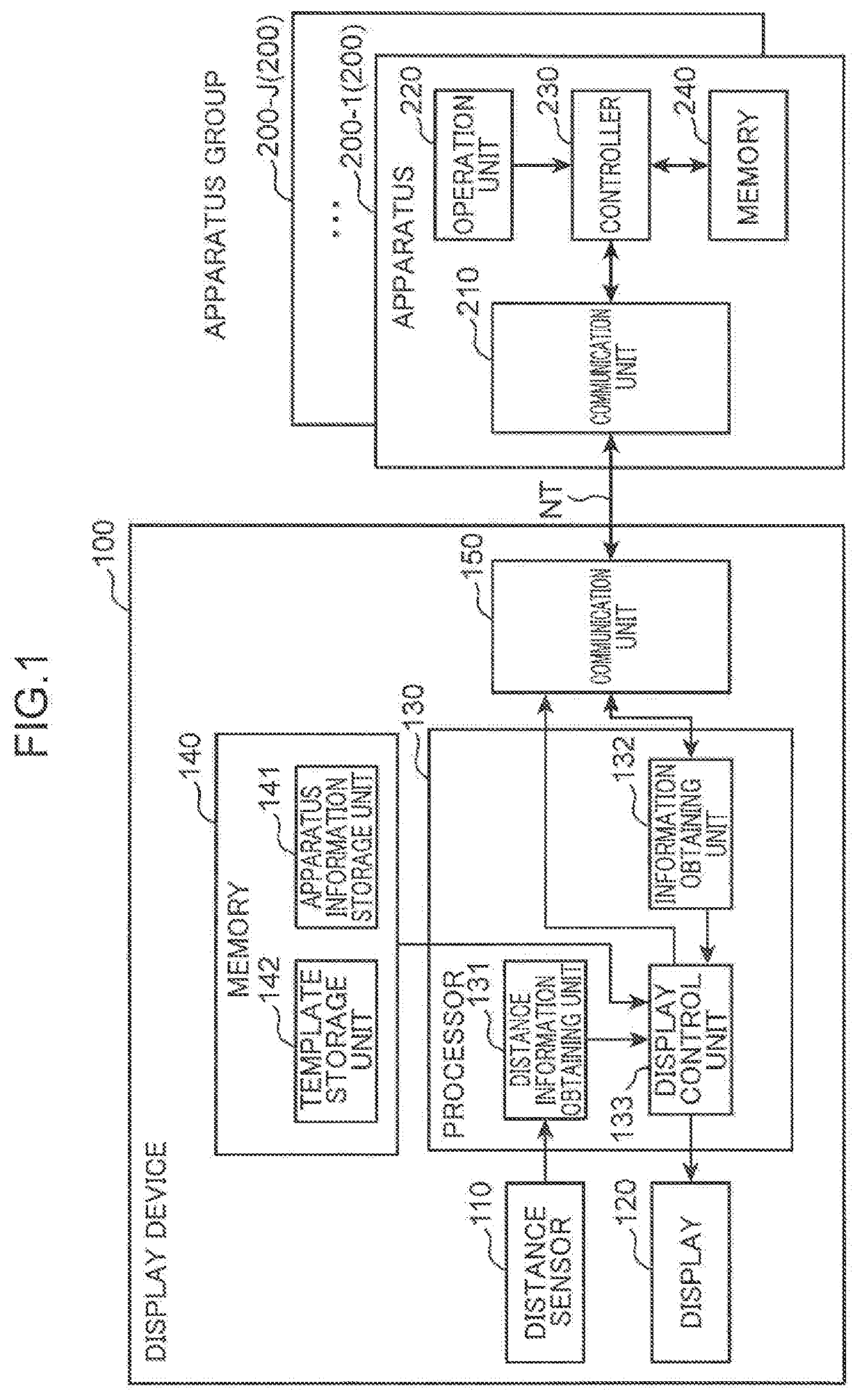
[0069]FIG. 1 is a block diagram showing a configuration of a display system including a display device 100 according to a first embodiment of the present disclosure. The display system shown in FIG. 1 includes the display device 100 and an apparatus group including a number J (J is an integer of one or more) of apparatuses 200_1 to 200_J. Hereinafter, when collectively referring to the apparatuses 200_1 to 200_J, a reference sign “200” is attached.
[0070]The display system is a system which is installed in, for example, a building such as a house or an office building and presents a state of the apparatus 200 to a user through the display device 100. The display system is also capable of accepting operation of a certain apparatus 200 by a user through the display device 100 and causing the user to remotely operate the apparatus 200 in question.
[0071]The house is, for example, a collective housing or a detached house. The display device 100 is, for example, a panel type display device...
second embodiment
[0141]In a second embodiment, an apparatus 200 which satisfies a predetermined condition is selected based on an operation history of the apparatus 200. FIG. 9 is a block diagram showing a configuration of a display system including a display device 100A according to the second embodiment of the present disclosure. In the present embodiment, the same constituent elements as those of the first embodiment are given the same reference signs to omit description thereof. Additionally, for operation of the display device 100A in the present embodiment, the flow shown in FIG. 7 or FIG. 8 is adopted.
[0142]FIG. 9 is different from FIG. 1 in that an operation history storage unit 143 is further provided in the memory 140. The operation history storage unit 143 stores operation histories of the number J of apparatuses 200. FIG. 10 is a diagram showing a configuration of an operation history table T100 constituting an operation history of the apparatus 200.
[0143]For each of the number J of appa...
third embodiment
[0158]In a third embodiment, a condition in accordance with identification information of a user is adopted as a predetermined condition to select the apparatus 200. FIG. 11 is a block diagram showing a configuration of a display system including a display device 100B according to the third embodiment of the present disclosure. In the present embodiment, the same constituent elements as those of the first and second embodiments are given the same reference signs to omit description thereof.
[0159]FIG. 11 is different from FIG. 1 in that a camera 160 and a microphone 170 are further provided in the display device 100B, an identification information obtaining unit 134 is further provided in the processor 130, and a user related information storage unit 144 is further provided in the memory 140. The user related information storage unit 144 stores user related information indicative of one or more users and one or more apparatuses 200 associated with each user in advance. FIG. 12 is a d...
PUM
 Abstract
Description
Claims
Application Information
 - R&D
- Intellectual Property
- Life Sciences
- Materials
- Tech Scout
- Unparalleled Data Quality
- Higher Quality Content
- 60% Fewer Hallucinations
Browse by: Latest US Patents, China's latest patents, Technical Efficacy Thesaurus, Application Domain, Technology Topic, Popular Technical Reports.
© 2025 PatSnap. All rights reserved.Legal|Privacy policy|Modern Slavery Act Transparency Statement|Sitemap|About US| Contact US: help@patsnap.com