

Image forming apparatus
- Summary
- Abstract
- Description
- Claims
- Application Information
AI Technical Summary
Benefits of technology
Problems solved by technology
Method used
Image

Examples
Embodiment Construction
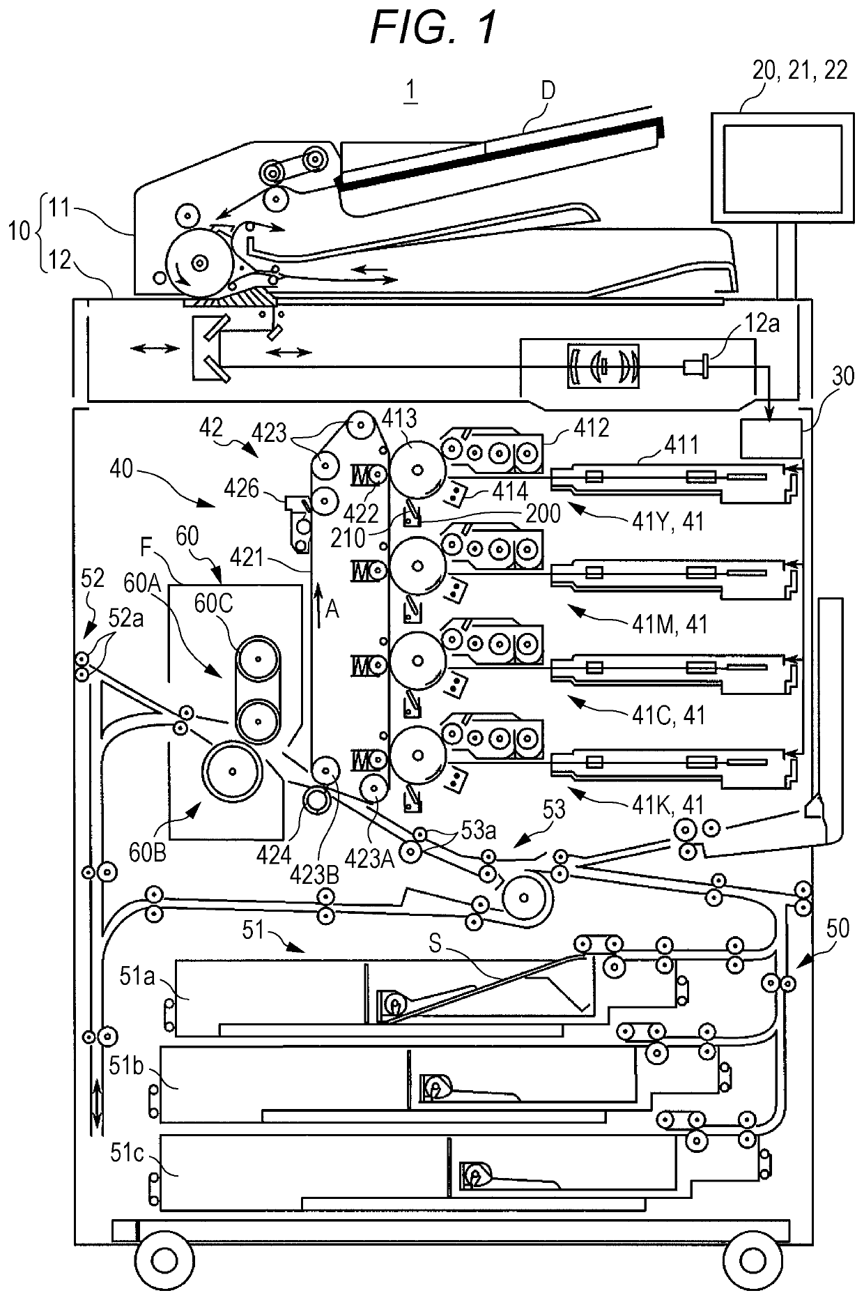
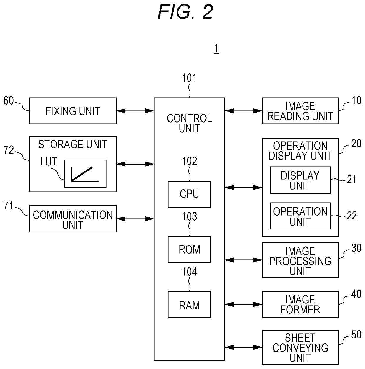
[0026]Hereinafter, one or more embodiments of the present invention will be described with reference to the drawings. However, the scope of the invention is not limited to the disclosed embodiments. FIG. 1 is a view schematically showing an entire configuration of an image forming apparatus 1 according to an embodiment of the present invention. FIG. 2 is a view showing a main part of a control system of the image forming apparatus 1.
[0027]The image forming apparatus 1 shown in FIGS. 1 and 2 is an intermediate-transfer color image forming apparatus using an electrophotographic process technology. That is, the image forming apparatus 1 primarily transfers respective color toner images of yellow (Y), magenta (M), cyan (C), and black (K) formed on a photosensitive drum 413 to an intermediate transfer belt 421, superimposes the four color toner images on the intermediate transfer belt 421, and then secondary transfers the toner images onto a sheet S, to form an image.
[0028]Further, to th...
PUM
 Abstract
Description
Claims
Application Information