Axial Piston-Type Hydraulic Rotary Machine

Active Publication Date: 2021-09-09
HITACHI CONSTR MASCH CO LTD
View PDF0 Cites 0 Cited by
  • Summary
  • Abstract
  • Description
  • Claims
  • Application Information

AI Technical Summary

Benefits of technology

[0012]According to the present invention, an inner circumferential surface (the piston sliding surface) of each cylinder hole is formed as the compound layer-removed hole from which the compound layer is removed. Then, the compound layer-removed surface from which the compound layer that is located on the front surface side of the aforementioned nitriding layer is removed is fo

Problems solved by technology

However, there are cases where the high-hardness compound layer remains on the opening end (the inlet) side of the cylinder hole.
Consequently, there is a problem that the piston

Method used


Image

  • Axial Piston-Type Hydraulic Rotary Machine
  • Axial Piston-Type Hydraulic Rotary Machine
  • Axial Piston-Type Hydraulic Rotary Machine

Examples


first embodiment

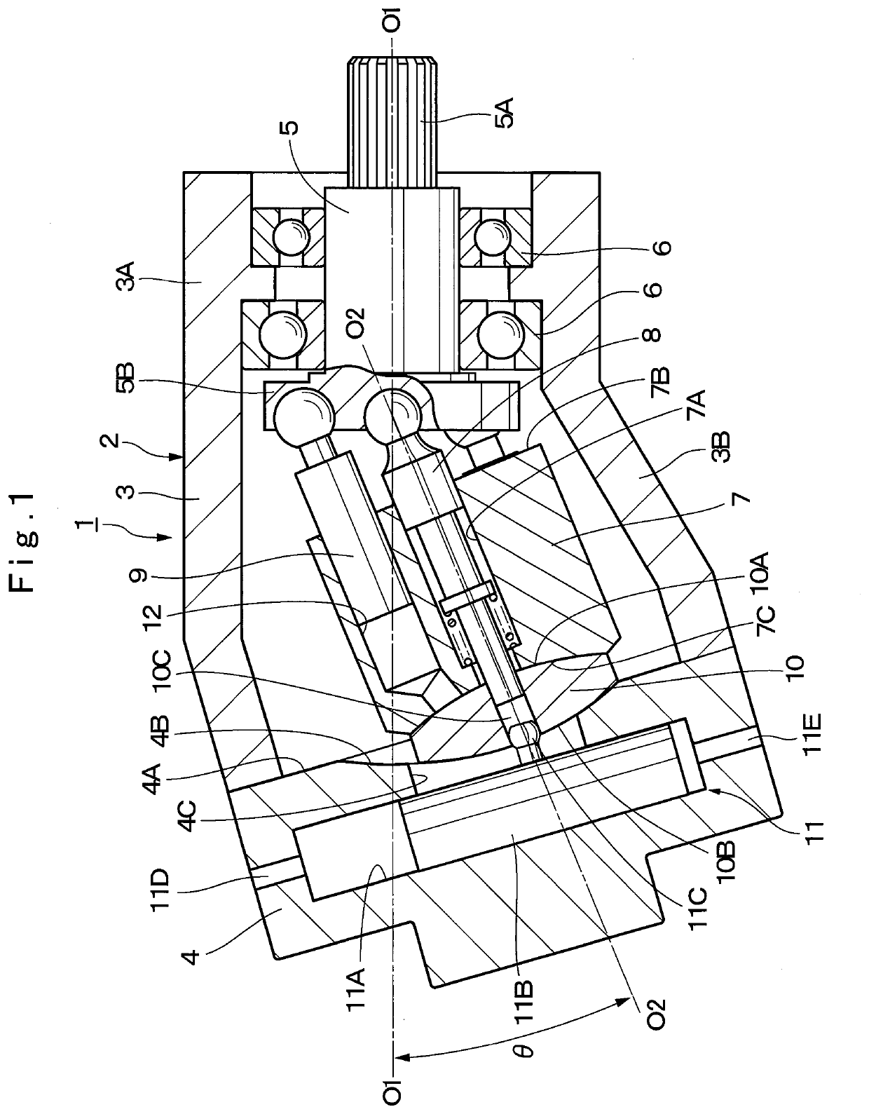
[0020]Here, FIG. 1 to FIG. 5 show the present invention. In FIG. 1, a hydraulic pump 1 that is configured by a variable displacement-type inclined shaft-type hydraulic rotary machine has a casing 2 that configures an outer shell thereof. This casing 2 is configured by a casing body 3 that exhibits a bent tubular shape and a later described head casing 4. The hydraulic pump 1 supplies pressurized oil toward various kinds of hydraulic equipment (none of them are shown) that are connected on the downstream side of a hydraulic conduit while sucking hydraulic oil from a hydraulic oil tank.

[0021]The casing body 3 of the casing 2 is configured by a bearing part 3A that is located on one side of an axial direction and is formed into an almost cylindrical shape and a cylinder block accommodating part 3B that incliningly extends from the other end of the bearing part 3A. The head casing 4 is attached to the other end of this cylinder block accommodating part 3B. This head casing 4 is provided...

second embodiment

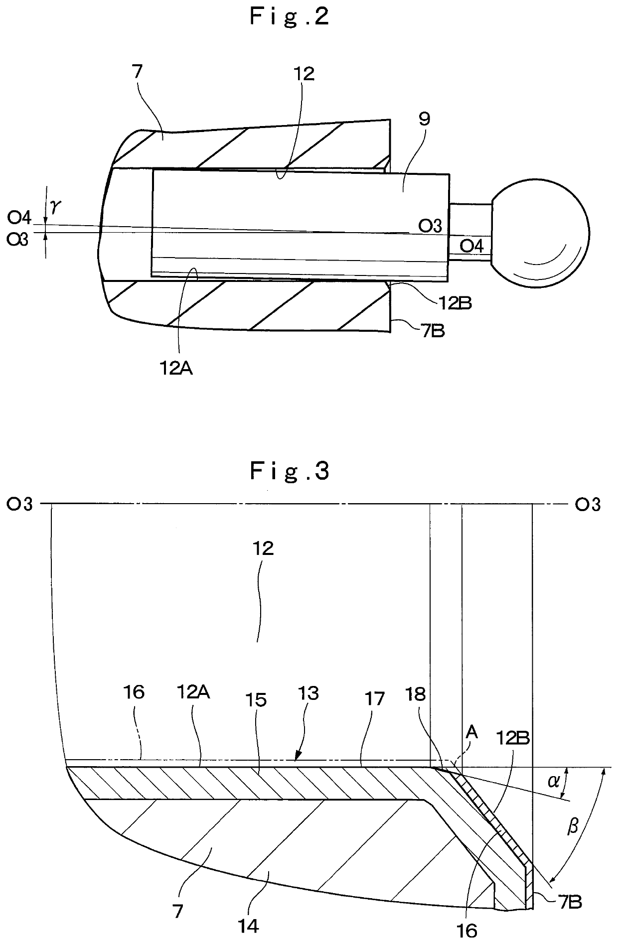
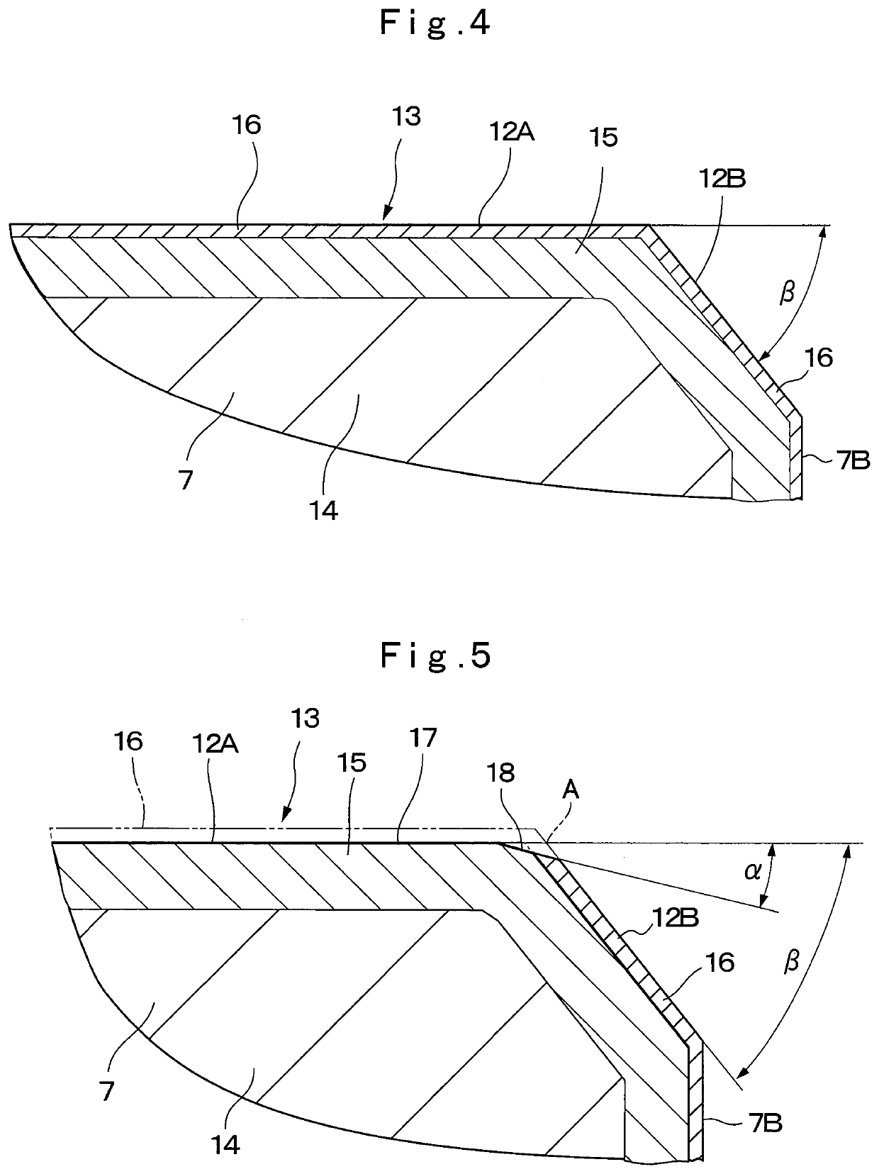
[0062]Thus, the piston sliding surface 12A of each cylinder hole 12 is formed as the compound layer-removed hole 17 by removing the compound layer 16 that is located on the front surface side of the nitriding layer 13 by using the polishing means such as, for example, the honing and so forth also in the second embodiment that is configured in this way. Then, the compound layer-removed surface 21 is formed on the part A where the compound layer-removed hole 17 and the cylinder inlet side tapered surface 12B of each cylinder hole 12 intersect by using the polishing means such as, for example, the honing and so forth.

[0063]The compound layer-removed surface 21 is formed by abrasively machining the part A where the compound layer-removed hole 17 and the cylinder inlet side tapered surface 12B intersect into the curved-surface shape in such a manner that its angle is gradually widened particularly in the second embodiment. For this reason, remaining of the high-hardness compound layer 16...


PUM

PropertyMeasurementUnit
Currentaaaaaaaaaa
Digital informationaaaaaaaaaa

Abstract

A nitriding layer (13) is formed on the front surface side of a base material of a cylinder block (7) including an opening side end surface (7B) and each cylinder hole (12). Then, a piston sliding surface (12A) of each cylinder hole (12) is formed as a compound layer-removed hole (17) by removing a compound layer (16) that is located on the front surface side of the nitriding layer (13) by using polishing means such as, for example, honing and so forth. Further, a compound layer-removed surface (18) is formed on a part (A) where a compound layer-removed hole (17) and a cylinder inlet side tapered surface (12B) of each cylinder hole (12) intersect by using the polishing means such as, for example, the honing and so forth. This compound layer-removed surface (18) is formed as a tapered-state inclined surface of an angle α.

Description

TECHNICAL FIELD[0001]The present invention relates to an axial piston-type hydraulic rotary machine that is used as a hydraulic pump, a hydraulic motor in, for example, civil engineering machinery, construction machinery and other general machinery.BACKGROUND ART[0002]In general, a hydraulic rotary machine (for example, a fixed displacement type or variable displacement type axial piston-type hydraulic rotary machine) that is used as the hydraulic pump or the hydraulic motor in the construction machinery such as a hydraulic excavator and the general machinery is known. The axial piston-type hydraulic rotary machine of this kind according to conventional art is configured by including a casing, a rotational shaft that is rotatably provided in the casing, a cylinder block that is rotatably provided in the aforementioned casing so as to rotate together with the rotary shaft and in which a plurality of cylinder holes that are separated from one another in a circumferential direction and...

Claims


Application Information

Patent Timeline
IPC IPC(8): F04B53/16F04B1/2035C23C8/24
CPCF04B53/166F04B1/303C23C8/24F04B1/2035F03C1/0652F05C2253/12F03C1/24F04B1/24F05B2210/11F04B1/2064F04B1/128F04B1/2042Y10S417/00F04B1/2078F04B1/12F04B39/122F04B39/126F04B1/03F04B1/20
Inventor YAMADA, TSUYOSHIYABUUCHI, YOSHITOMOOKUNO, NAOYUKI
Owner HITACHI CONSTR MASCH CO LTD
Why Eureka
Try Eureka