Substrate Coated with a Layered Structure Comprising a Tetrahedral Carbon Layer and a Softer Outer Layer

a technology of tetrahedral carbon and substrate, applied in the direction of natural mineral layered products, superimposed coating processes, transportation and packaging, etc., can solve the problems of high high roughness achieve positive influence on the running-in wear behaviour of tetrahedral carbon coating, the effect of reducing wear on the counterbody of the coated metal substra

Active Publication Date: 2008-09-11
SULZER METAPLAS
View PDF10 Cites 68 Cited by
  • Summary
  • Abstract
  • Description
  • Claims
  • Application Information

AI Technical Summary

Benefits of technology

[0060]When a metal substrate coated with such a hard and rough layer is used for applications whereby friction is created on a counterbody, the wear on the counterbody of the coated metal substrate will be high.
[0061]To reduce the wear on the co...

Problems solved by technology

A disadvantage of tetrahedral carbon coatings is their high roughness.
In case tetrahedral car...

Method used


Image

  • Substrate Coated with a Layered Structure Comprising a Tetrahedral Carbon Layer and a Softer Outer Layer
  • Substrate Coated with a Layered Structure Comprising a Tetrahedral Carbon Layer and a Softer Outer Layer

Examples


first embodiment

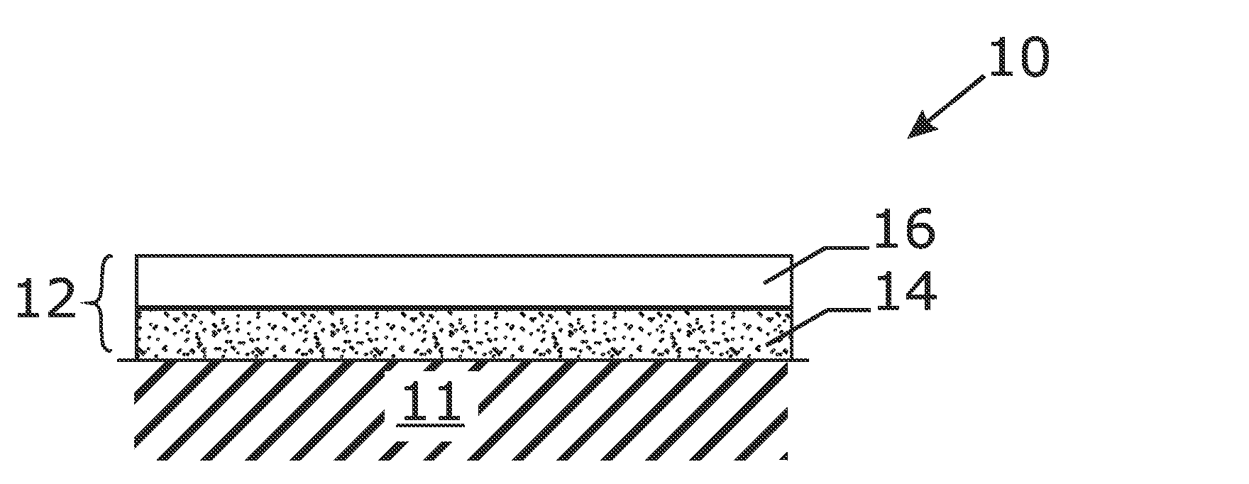
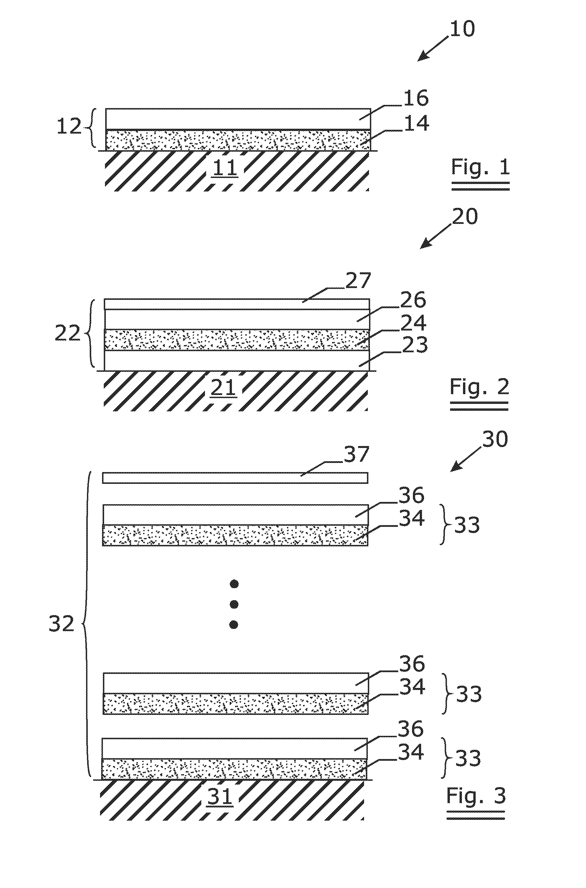
[0067]FIG. 1 gives a cross-section of a coated metal substrate 10 according to the present invention. A metal substrate 11 is coated with a layered structure 12.

[0068]The layered structure comprises[0069]an intermediate layer 14 deposited on the metal substrate 10. The intermediate layer comprises a tetrahedral carbon layer.[0070]an amorphous carbon layer 16 deposited on the intermediate layer 14. The amorphous carbon layer comprises a hydrogenated amorphous carbon layer, a-C:H.

[0071]The intermediate layer 14 has a thickness of 1 μm and a Young's modulus of 400 GPa.

[0072]The amorphous carbon layer 16 has a thickness of 1 μm and a Young's modulus of 170 GPa.

[0073]In an alternative embodiment of the present invention, the amorphous carbon layer 16 comprises a diamond-like nanocomposite layer comprising two interpenetrating networks a-C:H and a-Si:O.

[0074]This amorphous carbon layer 16 has a thickness of 1 μm and a Young's modulus of 150 GPa.

second embodiment

[0075]FIG. 2 shows the cross-section of a coated metal substrate 20 according to the present invention. A metal substrate 21 is coated with a layered structure 22.

[0076]The layered structure comprises[0077]an adhesion promoting layer 23 deposited on the metal substrate. The adhesion promoting layer 23 comprises for example a chromium or chromium based layer or a titanium or titanium based layer;[0078]an intermediate layer 24 deposited on the adhesion promoting layer 23. The intermediate layer 24 comprises a tetrahedral carbon layer;[0079]an amorphous carbon layer 26 deposited on the intermediate layer 24. The amorphous carbon layer comprises a hydrogenated amorphous carbon layer, a-C:H.

[0080]The adhesion promoting layer 23 has a thickness of 0.2 μm; the intermediate layer 24 has a thickness of 1 μm and a Young's modulus of 400 GPa and the amorphous carbon layer 26 has a thickness of 1 μm and a Young's modulus of 170 GPa.

[0081]Possibly, the layered structure 22 further comprises a to...

third embodiment

[0082]FIG. 3 shows the cross-section of a coated metal substrate 30 according to the present invention.

[0083]A metal substrate 31 is coated with a layered structure 32 comprising a number of periods 33. Each period comprises an intermediate layer 34 and an amorphous carbon layer 36. The number of periods is for example 10.

[0084]Possibly, the layered structure 32 further comprises a top layer 37.


PUM

PropertyMeasurementUnit
Pressureaaaaaaaaaa
Pressureaaaaaaaaaa
Pressureaaaaaaaaaa

Abstract

The invention relates to a metal substrate coated at least partially with a layered structure. The layered structure comprises an intermediate layer deposited on the metal substrate and an amorphous carbon layer deposited on the intermediate layer. The amorphous carbon layer has a Young's modulus lower than 200 GPa. The intermediate layer comprises a tetrahedral carbon layer having a Young's modulus higher than 200 GPa. The invention further relates to a method to reduce the wear on a counterbody of a metal substrate coated with a tetrahedral carbon coating.

Description

FIELD OF THE INVENTION[0001]The invention relates to a metal substrate coated with a layered structure comprising an intermediate layer deposited on the substrate and an amorphous carbon layer deposited on the intermediate layer. The intermediate layer comprises a tetrahedral carbon layer.BACKGROUND OF THE INVENTION[0002]The term Diamond Like Carbon (DLC) describes a group of materials comprising carbon with structures and properties resembling that of diamond. Some examples of Diamond Like Carbon coatings are a-C, a-C:H, i-C, ta-C and ta-C:H coatings.[0003]As DLC has many attractive properties including high hardness, chemical inertness, high thermal conductivity, good electrical and optical properties, biocompatibility and excellent tribological behavior, DLC has attracted a considerable interest as coating material.[0004]A rough classification of DLC coatings is given by the fractions of Sp3 bonding. Tetrahedral carbon coatings have a high fraction of Sp3 bonded carbon, whereas a...

Claims


Application Information

Patent Timeline
IPC IPC(8): B32B9/04C09D7/00
CPCC23C16/0272Y10T428/2495Y10T428/30C23C16/26C23C28/322C23C28/343C23C28/347C23C28/42
Inventor DEKEMPENEER, ERIK
Owner SULZER METAPLAS
Why Eureka
Try Eureka