Structure for connecting tubular member to fuel tank

a technology for connecting tubular parts and fuel tanks, applied in branching pipes, machines/engines, packaging, etc., to achieve the effect of enhancing air tightness

Inactive Publication Date: 2002-09-19
SUMITOMO RIKO CO LTD
View PDF0 Cites 68 Cited by
  • Summary
  • Abstract
  • Description
  • Claims
  • Application Information

AI Technical Summary

Benefits of technology

[0006] Therefore, it is an object of the present invention to provide a structure to connect a resin tubular member to a resin fuel tank, having good fuel gas permeability resistance, more particularly, good gasoline permeability resistance at a connecting portion therebeteen.
[0010] The securing strength and air-tightness between a tubular member and a cylindrical convex portion is brought by the annular projection bit into the inner peripheral surface of a cylindrical convex portion. However, as the tubular member is made of resin, in case that a tubular member has been press-fitted into the cylindrical convex portion for a long period, a tubular member is aged and is reduced in dimension. This results that the securing strength and the air-tightness between a tubular member and a cylindrical convex portion will be deteriorated, since the annular projection cannot sufficiently bites into the inner peripheral surface of a cylindrical convex portion. Therefore, preferably, a metallic cylindrical body is fixedly disposed in the inner peripheral surface of a tubular member at least at the press-fit portion, in order to prevent wear and decrease in dimension, resulted from aged press-fit portion of a tubular member. Meanwhile, in case that a tubular member is, for example, a hose connecting pipe, a hose is fitted onto the side of the other axial end of a tubular member, and a hose is securely fastened onto a tubular member with fastening band, or the like for the purpose to ensure securing or connecting strength and air-tightness. Thus, such measures should be taken against decrease in dimension and wear of the other axial end portion or the side of the other axial end of a tubular member resulted from aging, or securing strength and air-tightness between the hose and the tubular member would be deteriorated. Therefore, it is effective to secure a metallic cylindrical body in a tubular member along the entire length thereof, or substantially along the entire length thereof.
[0012] A flange is usually provided onto the outer peripheral surface of a tubular member, in order to limit a lengthwise portion of the tubular member to be press-fitted in the cylindrical convex portion. That is, a typical tubular member comprises a tubular body and a range provided on the outer peripheral surface of a tubular body. It will further enhance air-tightness between a tubular member and a fuel tank, to dispose an elastic annular sealing member or elastic annular sealing members between a flange and an outer face of a fuel tank.

Problems solved by technology

However, in the connecting structure shown in FIG. 9, evaporated gasoline or gasoline might penetrate in a clearance created between the outer surface of the connecting pipe C and the rim or the inner peripheral surface of the opening M, and might permeate through the HDPE flange C-1 having insufficient gasoline perability resistance (refer to arrows in FIG. 9), resulting in permitting evaporated gasoline (vapor fuel) to diffuse or flow out into the air.

Method used


Image

  • Structure for connecting tubular member to fuel tank
  • Structure for connecting tubular member to fuel tank
  • Structure for connecting tubular member to fuel tank

Examples


Embodiment Construction

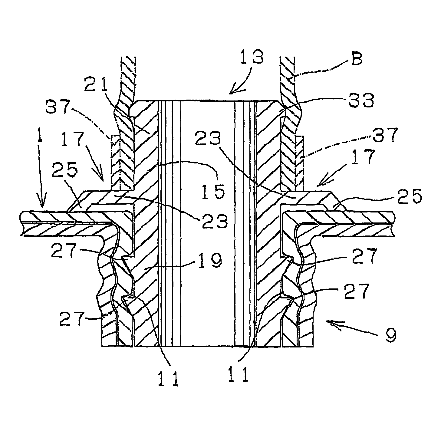
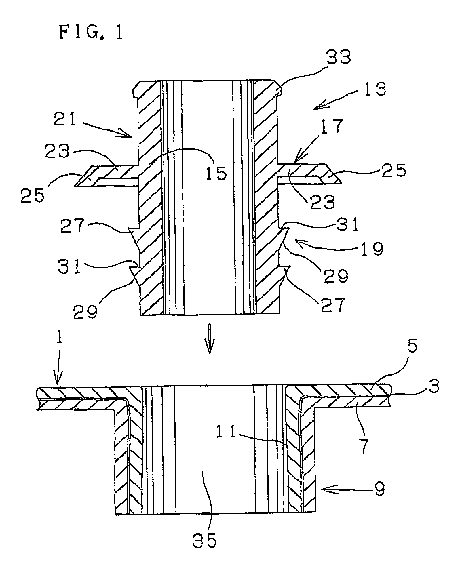
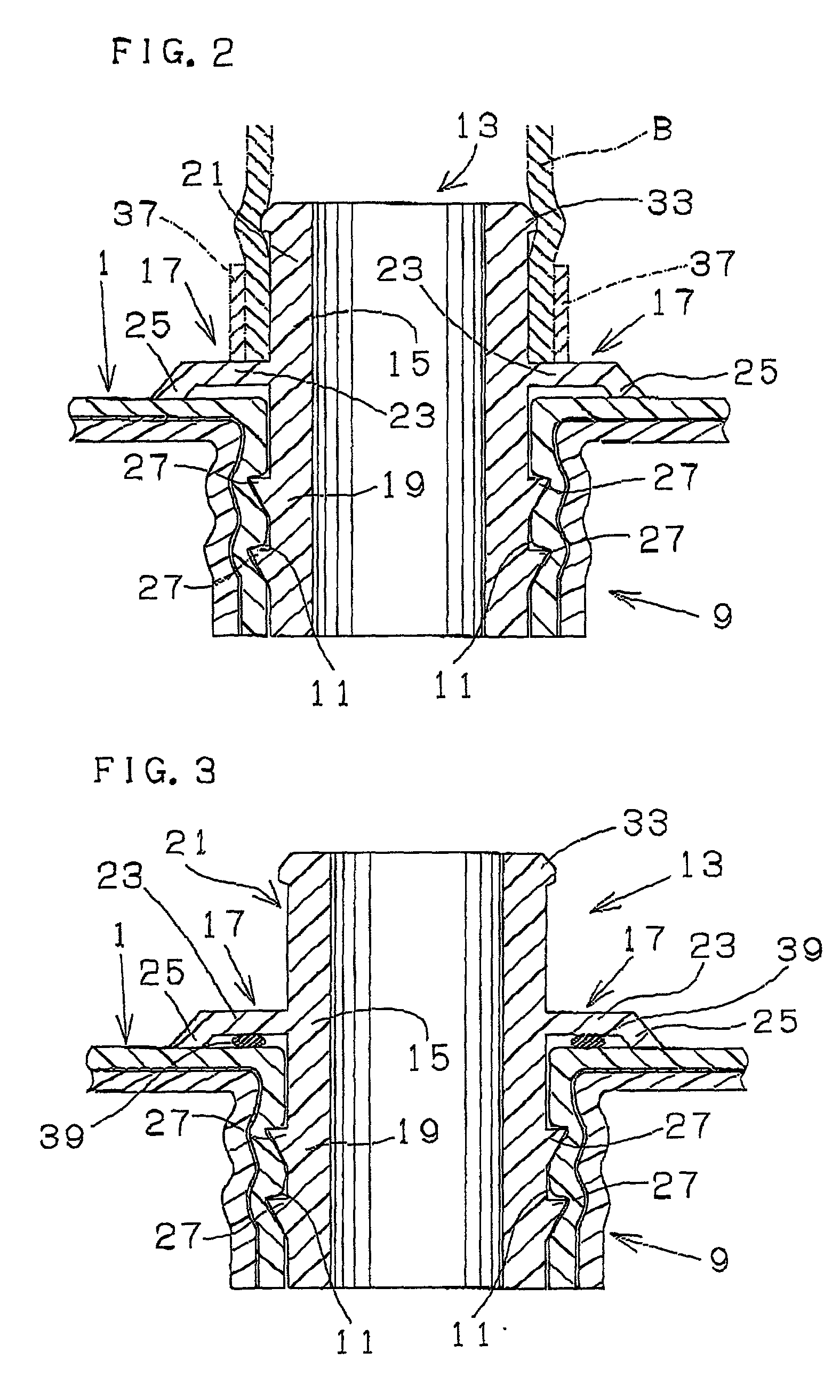
[0025] Referring to FIG. 1 and FIG. 2, it is understood that the present invention is applied for connecting structure between a fuel tank and a filler hose connecting pipe. A fuel tank 1 in this embodiment is blow-molded, and comprises multilayers of approximately 10 mm in thickness, wherein a middle gasoline barrier layer 3 made of PA is joined with material-to-material bond to an outer layer 5 made of HDPF, and to an inner layer 7 made of HDPE. An cylindrical convex portion 9, of which axial opposite ends are open, is formed extending inwardly in a fuel tank 1, so as to provide an opening thereof. The inner peripheral surface 11 of the cylindrical convex portion 9 has sufficient and satisfactory smoothness.

[0026] A filler hose connecting pipe 13 (tubular member) comprises a pipe body 15 and a flange 17 integrally formed therewith substantially at the axial longitudinal) center of the pipe body 15 on the outer peripheral surface thereof. The side in axial direction from the flange...


PUM

PropertyMeasurementUnit
thicknessaaaaaaaaaa
angleaaaaaaaaaa
structureaaaaaaaaaa

Abstract

An cylindrical convex portion of which opposite ends are open is integrally formed onto a fuel tank made of RDPE therewith so as to inwardly extend in the fuel tank, to provide an opening thereon. A press-fit portion of a filler hose connecting pipe made of PA as a tubular member is press-fitted in the cylindrical convex portion to connecting the tubular member to the fuel tank. At least one annular projection is provided on the outer peripheral surface of the press-fit portion of the tubular member so as to bite in the inner peripheral surface of the cylindrical connvex portion. A face of the annular projection in direction axially of one end of tubular member is formed so as to extend outwardly and inclinedly with respect to the axial direction of the tubular member form one end toward the other end thereof.

Description

BACKGROUND OF THE INVENTION[0001] The present invention relates to structure for connecting tubular member to fuel tank, such as hose connecting pipe or valve-housing, for example, for connecting to a fuel tank of an automobile.[0002] FIG. 8 shows an example of a fuel tank system which is installed in an automobile so that gasoline is fed to an engine. In this instance, gasoline is supplied in a fuel tank A through a filler hose B and a connecting pipe C, by means of a fueling gun (not shown) inserted into a filler pipe D connected to a filler hose B. Gasoline in the fuel tank A is fed to an engine by a fuel pump E through a feed hose F, and excess gasoline is collected through a return hose G into the fuel tank A. A comunication pipe D-1 is branched from the upper portion of the filler pipe D, and a communication hose H, which is connected to the communication pipe D-1, is attached at the tip end portion thereof via a connecting pipe 1 to the fuel tank A. The tip end portion of the...

Claims


Application Information

Patent Timeline
Patent Type & Authority Applications(United States)
IPC IPC(8): B29C65/50B29C65/56B60K15/03B60K15/035B60K15/04F02M37/00F16L37/00F16L37/02F16L37/08F16L47/28
CPCB29C65/5057B29C65/565B29C2793/0018B29L2031/7172B60K15/03177B60K15/035B60K15/04B60K2015/03453F16L37/008F16L37/02F16L47/28B29C66/53247B29C65/4815B29C66/8322B29C66/71B29K2077/00B29K2023/065B29K2023/086B29C66/112B29C66/1122B29C66/131B29C66/232B29C66/72321B29C66/7234
Inventor MLYAJIMA, ATSUOITO, TOMOHIDEITO, HIROAKI
Owner SUMITOMO RIKO CO LTD
Why Eureka
Try Eureka