Ceramic armour and method of construction

a technology of ceramic armour and construction method, which is applied in the field of armor, can solve the problems of bulging deformation of the back surface of the armor, insufficient protection or any protection against armor piercing and/or high-energy projectiles, so as to improve the penetration resistance, reduce deformation, and high-energy projectiles

Inactive Publication Date: 2012-07-12
STRIKE FACE TECH
View PDF8 Cites 22 Cited by
  • Summary
  • Abstract
  • Description
  • Claims
  • Application Information

AI Technical Summary

Benefits of technology

[0018]It is an object of the invention to provide an armor that is lightweight and relatively thin, yet provides protection against armor piercing and / or high energy projectiles. It is a further object of the present invention to provide an armor where the armor can be used as a body armor or as protection for vehicles or other objects with reduced deformation and improved penetration resistance when impacted by armor piercing and / or high energy projectiles.

Problems solved by technology

However, previous armors are much too heavy or too bulky or too expensive or they do not provide sufficient protection or any protection against armor piercing and / or high-energy projectiles.
When a bullet strikes these armors, the impact produces a bulge which deforms the back surface of the armor.
Since the armor is worn adjacent to the body, this bulge, or deformation, projects into the body of the wearer which can cause injury to the wearer, known as behind armor blunt trauma.
U.S. Pat. No. 7,150,217 issued to Kershaw discloses an armor designed for lower velocity impacts as in protective equipment for sports or as a shoulder rest for a gun butt recoil, which is not capable of withstanding high velocity ballistic threats.
U.S. Patent Publication 2006 / 0065111 to Park et al. describes various combinations of ballistic fabric but does not address the incorporation of metallic or ceramic layers.

Method used


Image

  • Ceramic armour and method of construction
  • Ceramic armour and method of construction
  • Ceramic armour and method of construction

Examples


example 1

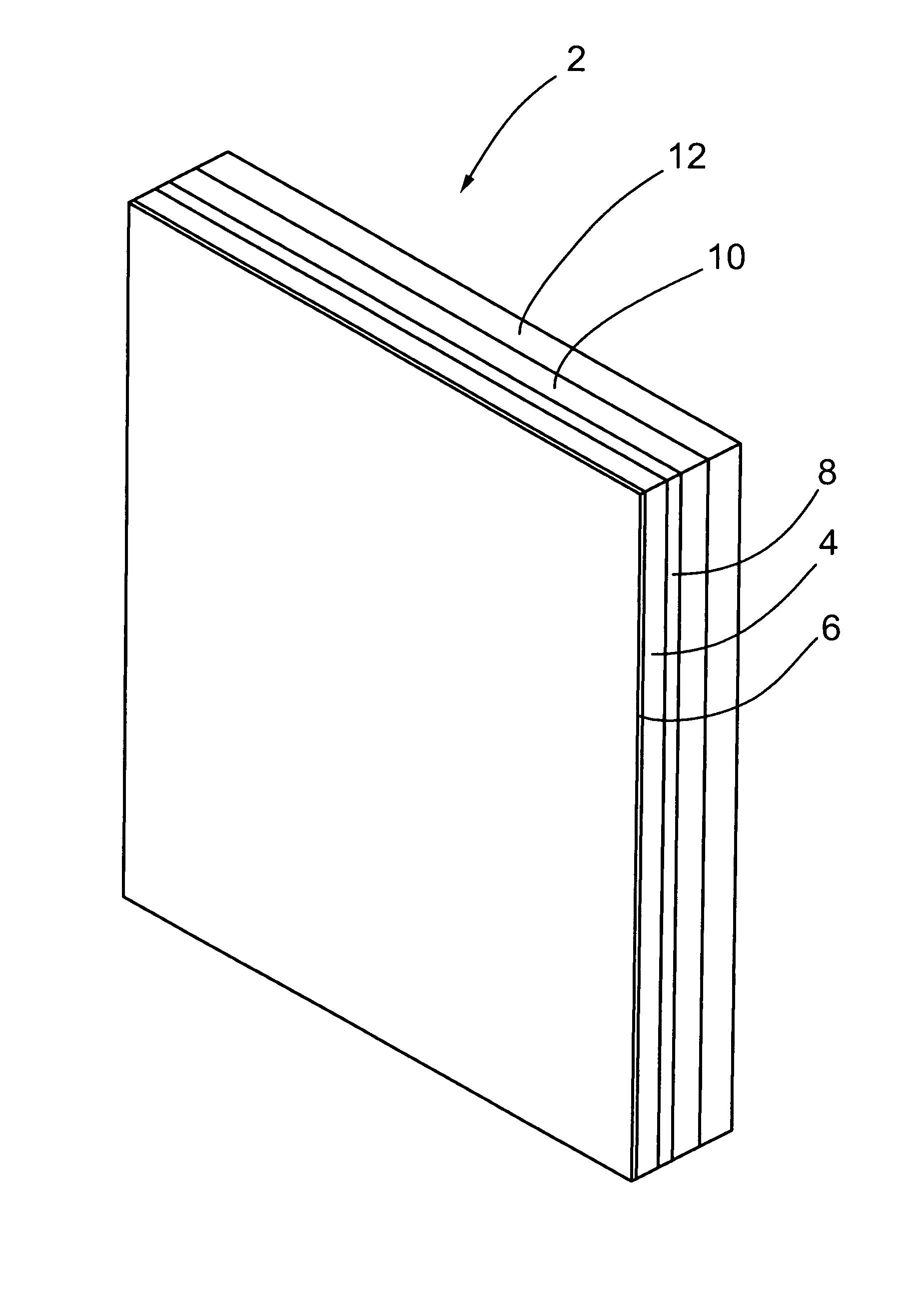
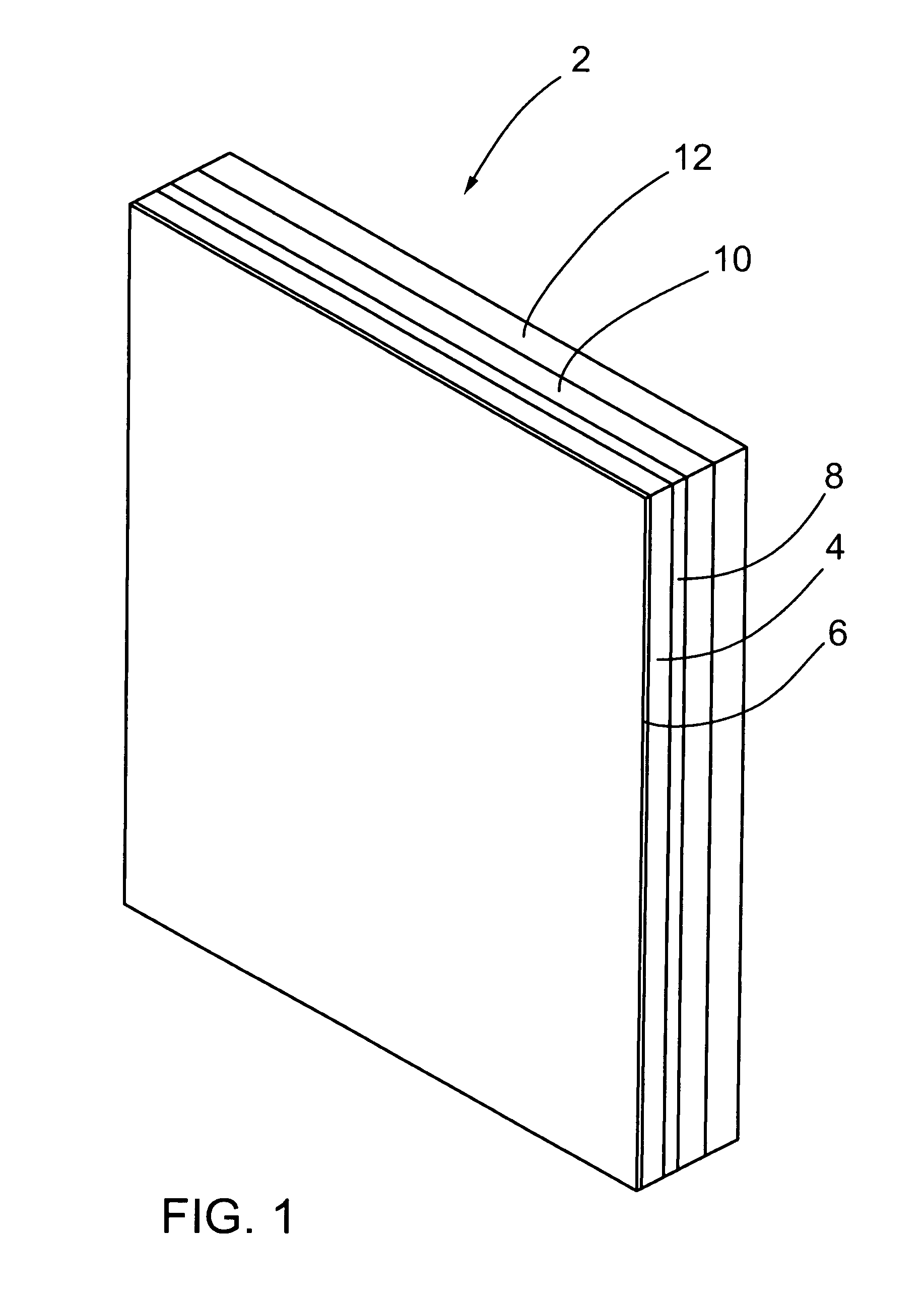
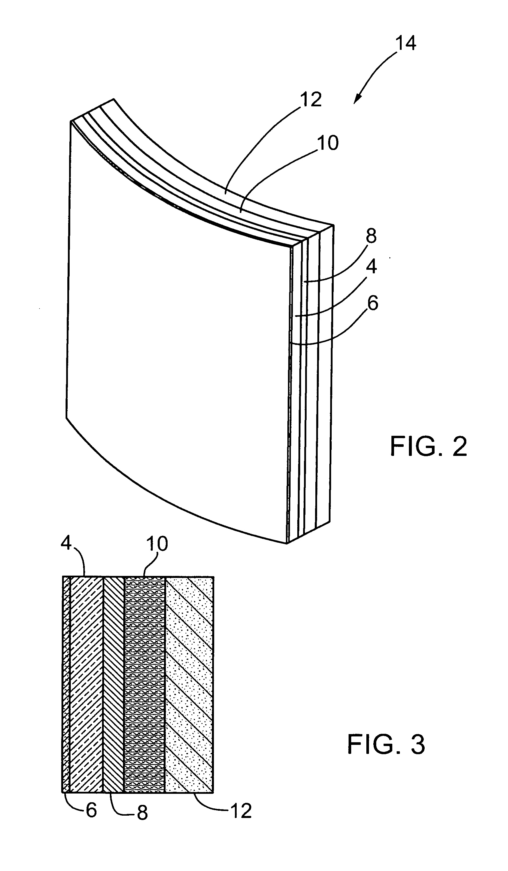
[0050]A multi-component armor plate has a confinement layer 6, ceramic layer 4 and first metal layer 8 that is 250 mm wide and 300 mm in height. The ballistic composite layer 10, a second metal layer 22 and anti-trauma layer 12 have dimensions of 250 mm in width by 300 mm in height. The total mass is approximately 4.8 kg.

[0051]In Example 1, the layers have the following thicknesses:

ThicknessMaterial2mmConfinement Layer (S-Glass with Structural Adhesive)11.1mmCeramic Layer (Silicon Carbide Manufactured by Saint-Gobain)1mmFirst Metal Layer—Titanium18.5mmBallistic composite layer consisting of 37 Layers ofKevlar ™ 129 with PVB Phenolic Matrix1mmSecond Metal Layer—Titanium15mmAnti-Trauma Layer

[0052]All layers in the example are bonded using a structural adhesive such as a urethane-based adhesive.

[0053]The design set out in Example 1 was evaluated using NIJ (National Institute of Justice) Standard 0101.04 (June 2001) (an applicable ballistic testing standard at the time of testing), whic...


PUM

PropertyMeasurementUnit
thicknessaaaaaaaaaa
thicknessaaaaaaaaaa
thicknessaaaaaaaaaa

Abstract

An armor for protection against armor piercing and/or high energy projectiles has a ceramic layer with a confinement layer on a front thereof. The ceramic layer is backed by a first metal layer and the first metal layer in turn is backed by a composite layer. A second optional confinement layer may be included between the ceramic and first metal layers. The composite layer is backed by an optional second metal layer, which in turn is backed by an optional anti-trauma layer. The armor is used to protect personnel and objects such as vehicles.

Description

CROSS REFERENCE TO RELATED APPLICATION[0001]This patent application is a Continuation-In-Part application of U.S. patent application Ser. No. 10 / 960,284 entitled CERAMIC ARMOUR AND METHOD OF CONSTRUCTION filed on Oct. 8, 2004 in the name of the same inventors, now issued as U.S. Pat. No. 7,540,228 on Jun. 2, 2009 which relates to, and claims the priority benefit from, U.S. Provisional Patent Application Ser. No. 60 / 514,621 filed on Oct. 8, 2003 entitled CERAMIC ARMOUR AND METHOD OF CONSTRUCTION, all of which are incorporated herein in its entirety.FIELD OF INVENTION[0002]This invention relates to an armor for protection against armor piercing and / or high energy projectiles where the armor has a nonporous ceramic layer which is struck by an incoming projectile, a solid nonporous metal layer backing the ceramic layer, and a ballistic composite layer backing the metal layer, where said composite layer is placed closest to the person or object being protected.BACKGROUND OF THE INVENTION...

Claims


Application Information

Patent Timeline
Patent Type & Authority Applications(United States)
IPC IPC(8): F41H5/04
CPCB32B9/005F41H5/0421B32B2571/02C04B35/63456C04B35/645C04B37/021C04B37/028C04B37/042C04B37/047C04B2235/667C04B2237/343C04B2237/36C04B2237/365C04B2237/403C04B2237/52C04B2237/704C04B2237/706B32B9/041
Inventor SALISBURY, CHRISTOPHER PETERKAUFMANN, CHRISTIANCRONIN, DUANE S.WORSWICK, MICHAEL JAMES
Owner STRIKE FACE TECH
Why Eureka
Try Eureka