Gear made of resin, and mold structure

a technology of resin and mold, applied in the direction of gearing details, other domestic articles, hoisting equipment, etc., can solve the problems of warpage and sink, above disadvantage is significant, etc., and achieve the effect of reducing the amount, reducing the amount of deformation such as warpage and sink in the opposite direction, and supplying effectively

Inactive Publication Date: 2005-04-26
ENPLAS CORP
View PDF11 Cites 75 Cited by
  • Summary
  • Abstract
  • Description
  • Claims
  • Application Information

AI Technical Summary

Benefits of technology

[0009]With such configuration, portions of tooth flanks tending to be sunk to a large extent are eliminated by the provision of the grooves and hence, only portions free from a sink and having a tooth flank accuracy can be meshed with a mating gear. In addition, according to the present invention, a thinned portion having the grooves defined therein is deformed in a decreased amount, and hence, the amount of deformation such as a warpage and a sink in an opposite direction is also decreased. Further, according to the present invention, the grooves are defined along the outer surfaces of the teeth and hence, a lubricant such as grease can be supplied effectively to tooth flanks by previously applying the lubricant in the grooves. Thus, the gear made of the resin can be rotated smoothly, and the wearing of the teeth of the gear can be inhibited, thereby enhancing the durability of the gear.

Problems solved by technology

The gear made of the resin is formed into a predetermined lightened shape by an injection molding, but the deformation such as a warpage and a sink may occur due to a difference between the amounts of material shrunk at molded portions.
Particularly, in a gear having a large tooth width as in the prior art shown in FIG. 3, the above disadvantage is significant.

Method used


Image

  • Gear made of resin, and mold structure
  • Gear made of resin, and mold structure
  • Gear made of resin, and mold structure

Examples


first application example

(First Application Example)

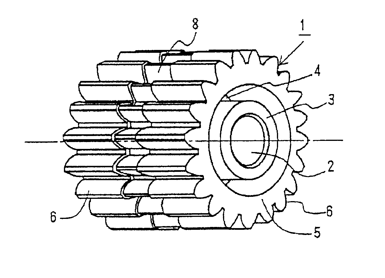
[0038]In the above-described embodiment, the groove 8 is defined at one point along the outer surface of each tooth 6 of the gear 1 to bisecting the teeth 6 in the widthwise direction. The present invention is not limited to this embodiment, and as shown in FIG. 7, grooves may be defined at two points along the outer surface of each tooth 6 to trisect the teeth, i.e., to divide the teeth into three sections. Alternatively, grooves may be defined at more than two points along the outer surface of each tooth 6 in the widthwise direction.

second application example

(Second Application Example)

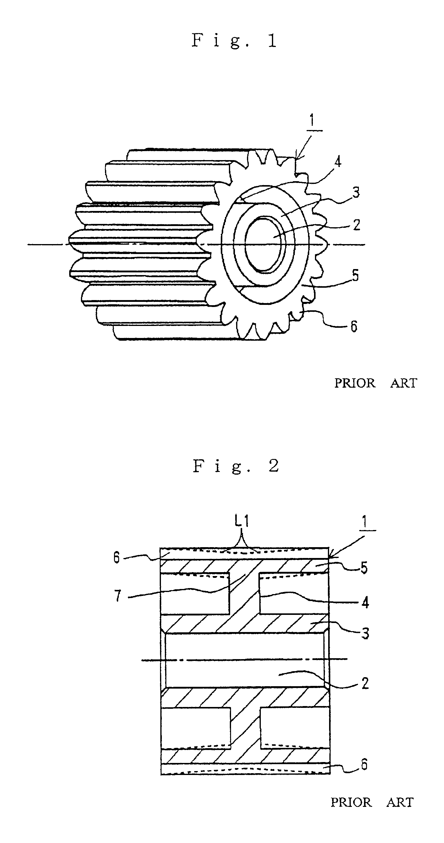
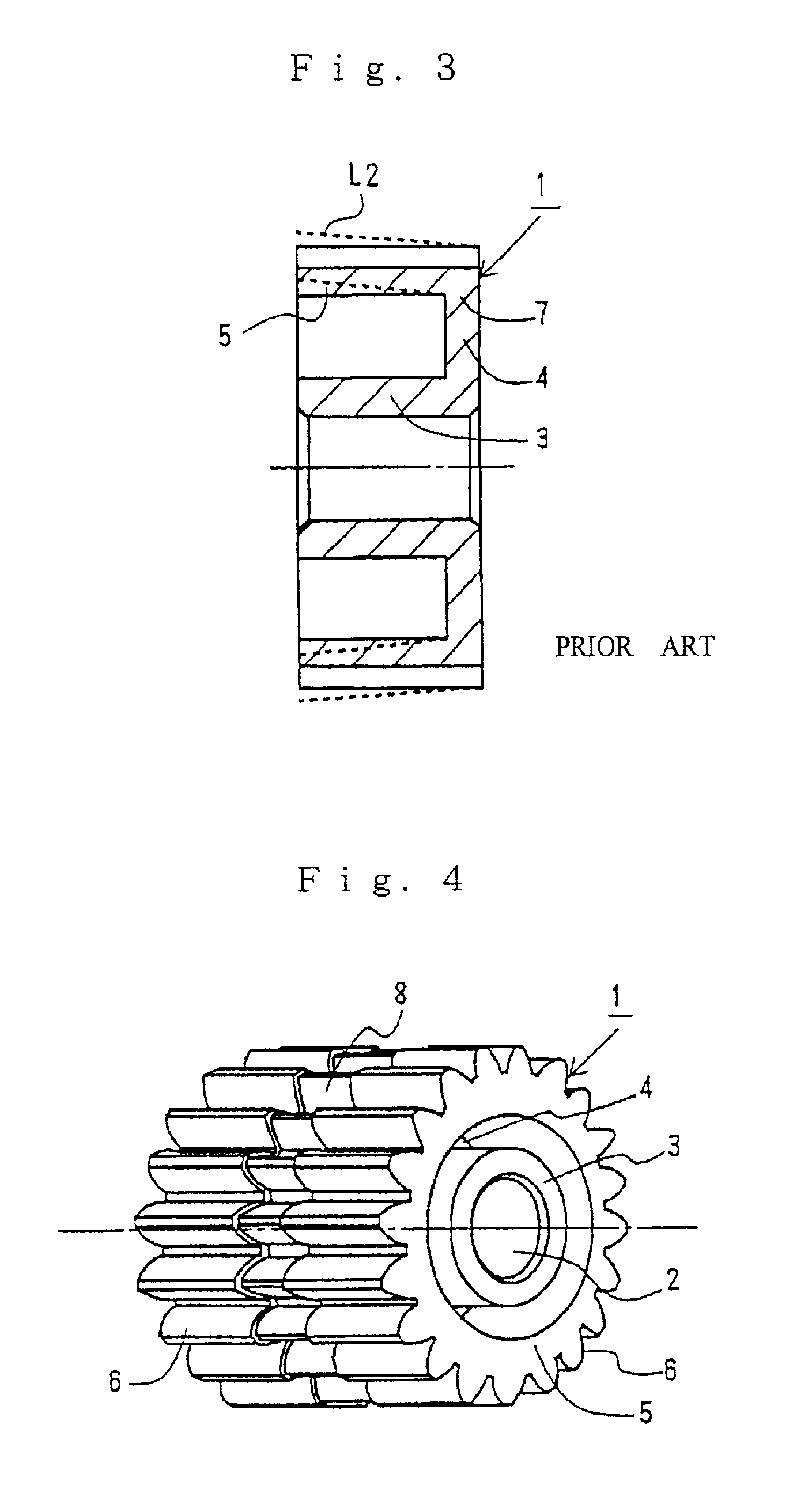
[0039]In the gear 1 made of the resin according to the above-described embodiment, the web 4 is formed at the substantially axially central portion of the boss 3. However, the present invention is not limited to this embodiment, and the web 4 may be formed at an axial end of the boss 3, and the boss 3 and the rim 5 may be connected to each other by the web 4. One groove 8 may be defined along the outer surface of each tooth 6 at substantially widthwise central portions of the teeth 5 of the gear 1 made of the resin. If the gear 1 is formed in the above manner, it is possible to inhibit the deformation of the rim 5 of the gear 1, called a warpage, as shown in FIG. 3, thereby enhancing the tooth flank accuracy.

application example

(Another Application Example)

[0040]The present invention is not limited to the shapes of the gears 1 according to the above-described embodiment and the application examples, and is applicable widely to an embodiment in which a rim 5 and a boss 3 are connected to each other by a web 4.

[0041]In the above-described embodiment and the application examples, at least one groove 8 is defined at the substantially widthwise central portion of the tooth 6, but the present invention is not limited to it, and the groove 8 may be defined at suitable location in consideration of the state of the tooth flank deformed, or may be defined at location where the lubricant can be supplied with a good effectiveness.

[0042]The grooves 8 having the substantially rectangular sectional shape have been illustrated in the above-described embodiment, but the prevent invention is not limited to this embodiment, and arcuate grooves 8A may be defined along the outer surfaces of the teeth 6 of the gear 1 as shown i...


PUM

PropertyMeasurementUnit
weightaaaaaaaaaa
shrinkageaaaaaaaaaa
widthaaaaaaaaaa

Abstract

A gear made of a resin includes a substantially cylindrical rim having a plurality of teeth formed around an outer periphery thereof, a boss formed about a rotational center of the rim, and a web connecting the boss and the rim to each other. At least one groove is defined along outer surface of each tooth to divide the tooth in a widthwise direction of the tooth. As a result, a portion of the gear, in which the grooves are defined, is deformed in a reduced amount, leading to a reduced amount of deformation such as a warpage or sink in the entire gear, thereby providing an enhancement in tooth flank accuracy. Since the grooves are defined along the outer surfaces of the teeth, a lubricant such as grease can be supplied effectively to tooth flanks by previously applying the lubricant in the grooves.

Description

BACKGROUND OF THE INVENTION[0001]1. Field of the Invention[0002]The present invention relates to a gear made of a resin, which is used widely in a power-transmitting mechanism for a duplicator, a printer, facsimile, an automobile part.[0003]2. Description of the Related Art[0004]A gear made of a resin is conventionally used in a power-transmitting mechanism for a duplicator, an automobile part and the like for the purpose of reducing the part cost and the weight and the operational sound. The gear made of the resin is formed into a predetermined lightened shape by an injection molding, but the deformation such as a warpage and a sink may occur due to a difference between the amounts of material shrunk at molded portions. For example, as shown in FIGS. 1 to 3, in a gear 1 formed of a resin so that a boss 3 and a rim 5 are connected to each other by a web 4, the amount of shrinkage or contraction of a connection 7 between the rim and the web 4 and the amount of shrinkage of an end of ...

Claims


Application Information

Patent Timeline
Patent Type & Authority Patents(United States)
IPC IPC(8): B29C33/44B29D15/00F16H55/17B29C33/20F16H55/06B29C45/44
CPCB29C33/44B29D15/00F16H57/04F16H55/17B29C33/20B29L2015/003F16H55/06Y10T74/19972F16H2055/065Y10S74/10Y10T74/19995Y10T74/19963
Inventor KIMIZUKA, GENICHI
Owner ENPLAS CORP
Why Eureka
Try Eureka