Ignition control device for internal combustion engine

a control device and internal combustion engine technology, applied in the direction of electric control, machines/engines, mechanical equipment, etc., can solve the problems of increased insufficient atomization of injected fuel, wasteful increase of the number of times of spark plug discharge, etc., to suppress wear and power consumption of the ignition device and sufficient combustion stability

Active Publication Date: 2016-04-26
HONDA MOTOR CO LTD
View PDF18 Cites 0 Cited by
  • Summary
  • Abstract
  • Description
  • Claims
  • Application Information

AI Technical Summary

Benefits of technology

[0007]It is an object of the present invention to provide an ignition control device for an internal combustion engine, which is capable of controlling the number of times of ignition operation such that it becomes neither too large nor too small, according to a flowing state of a mixture in a cylinder, to thereby ensure sufficient combustion stability and suppress wear and power consumption of an ignition device.

Problems solved by technology

The ignition control device is configured by taking into account a fact that atomization of injected fuel is liable to be insufficient, since the temperatures of a piston and a cylinder are relatively low when both the rotational speed of the engine and the load thereon are low.
However, it has been found that the relationship between the number of times of discharge and the advantageous effect of improvement in the ignition performance is not necessarily uniform, and particularly, the relationship largely depends on a flowing state of a mixture in the cylinder.
Therefore, when the flow velocity of the mixture is low, the number of times of discharge of the spark plug is wastefully increased in the state in which the advantageous effect of improvement in the ignition performance can be hardly obtained, whereby erosion of the spark plug proceeds to shorten the service life thereof and increase power consumption.

Method used


Image

  • Ignition control device for internal combustion engine
  • Ignition control device for internal combustion engine
  • Ignition control device for internal combustion engine

Examples


Embodiment Construction

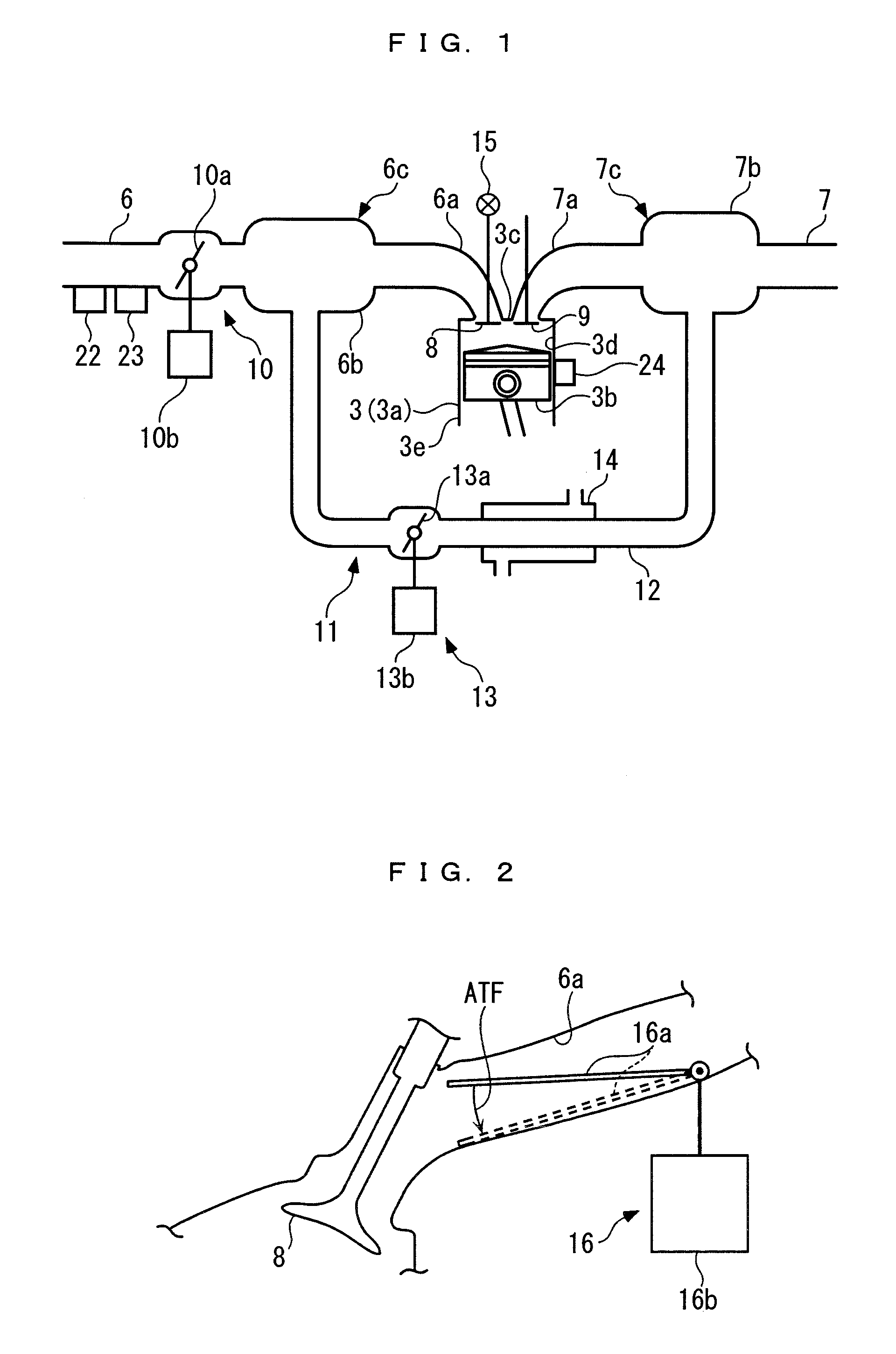
[0033]The invention will now be described in detail with reference to drawings showing a preferred embodiment thereof. FIG. 1 shows an internal combustion engine (hereinafter referred to as the “engine”) 3 to which the present invention is applied. The engine 3 is a gasoline engine that has e.g. four cylinders, and is installed on a vehicle, not shown. A combustion chamber 3d is defined between a piston 3b and a cylinder head 3c for each of cylinders 3a (only one of which is shown) of the engine 3.

[0034]An intake passage 6 is connected to each cylinder 3a via an intake ports 6a and an intake manifold 6c having an intake collector 6b, and an exhaust passage 7 is connected to each cylinder 3a via an exhaust port 7a and an exhaust manifold 7c having an exhaust collector 7b. The intake port 6a is provided with a fuel injection valve 4 (see FIG. 3) and the cylinder head 3c is provided with an ignition device 5 (see FIG. 3), on a cylinder-by-cylinder basis. Fuel injected from the fuel inj...


PUM


Abstract

An ignition control device for an internal combustion engine, which controls the number of times of ignition operation such that it becomes neither too large nor too small, according to a flowing state of a mixture in a cylinder. In the ignition control device, a target ignition timing is used as an in-cylinder flow parameter indicative of the strength of a tumble flow generated in a cylinder. When the target ignition timing is more advanced than a predetermined reference position, it is determined that the tumble flow is strong, and multiple ignition control is executed by setting the number of times of ignition to a plurality of times, whereas when the former is more retarded than the latter, it is determined that the tumble flow is not strong, and normal ignition control is executed by setting the number of times of ignition to only once.

Description

BACKGROUND OF THE INVENTION[0001]1. Field of the Invention[0002]The present invention relates to an ignition control device for an internal combustion engine, for controlling an ignition device capable of performing ignition operation a plurality of times in one combustion cycle.[0003]2. Description of the Related Art[0004]A conventional ignition control device for an internal combustion engine of this type is disclosed in Japanese Laid-Open Patent Publication No. H11-37030. This ignition control device detects the rotational speed of the engine and load thereon (opening degree of a throttle vale, for example), and increases the number of times of discharge (ignition operation) of a spark plug in one combustion cycle as the detected rotational speed is lower and also as the detected load is lower. The ignition control device is configured by taking into account a fact that atomization of injected fuel is liable to be insufficient, since the temperatures of a piston and a cylinder ar...

Claims


Application Information

Patent Timeline
Patent Type & Authority Patents(United States)
IPC IPC(8): F02P9/00F02D41/00F02P15/08F02D37/02
CPCF02P15/08F02D41/0002F02D37/02F02P9/002F02D2041/0015Y02T10/42Y02T10/40
Inventor KIMURA, NORITAKAIHARA, KOSUKE
Owner HONDA MOTOR CO LTD
Why Eureka
Try Eureka