System and method for operating an electrical energy storage system

a technology of electrical energy storage and electric energy, which is applied in the direction of electrochemical generators, safety/protection circuits, transportation and packaging, etc., can solve the problems of reducing the possibility of component degradation with an electric power system, increasing the possibility of degradation within the electrical energy storage system, etc., to increase the power output capacity increase the voltage potential of the electric energy storage system, and reduce the charge level

Active Publication Date: 2020-04-23
ESS TECHNOLOGY
View PDF28 Cites 1 Cited by
  • Summary
  • Abstract
  • Description
  • Claims
  • Application Information

AI Technical Summary

Benefits of technology

[0002]An electrical energy storage system may include electrical energy storage cells (e.g., battery cells) that are arranged in series and in parallel. Electrical energy storage cells that are arranged in series increase the voltage potential of the electric energy storage system. Electric energy storage cells that are arranged in parallel increase the power output capacity of the electric energy storage system. The electric energy storage cells of one electric energy storage cell stack may be charged to a level (e.g., voltage) such that the voltage of the one electric energy storage cell stack that includes the electric energy storage cells is lower or higher than levels of other electric energy storage cell stacks within the electrical energy storage system. The difference in charge stored between the electric energy storage cell stacks may cause larger amounts of current to flow from more highly charged electric energy storage cell stacks to electric energy storage cell stacks having lower charge levels. This may increase the possibility of degradation within the electrical energy storage system. Therefore, it may be desirable to provide a way of coupling electric energy storage cells from different electric energy storage cell stacks in a way that may reduce the possibility of degradation within the electric energy storage system.

Problems solved by technology

This may increase the possibility of degradation within the electrical energy storage system.
In particular, the approach may reduce the possibility of component degradation with an electric power system.

Method used


Image

  • System and method for operating an electrical energy storage system
  • System and method for operating an electrical energy storage system
  • System and method for operating an electrical energy storage system

Examples


Embodiment Construction

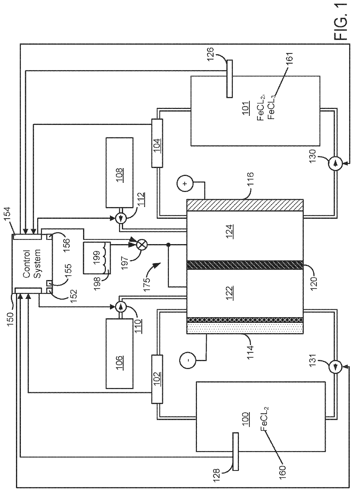
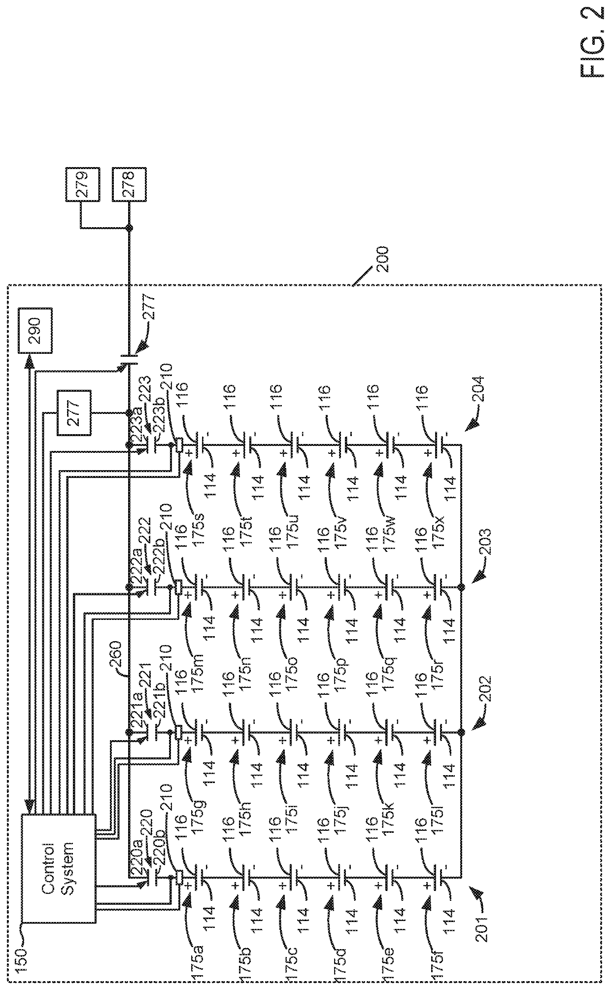
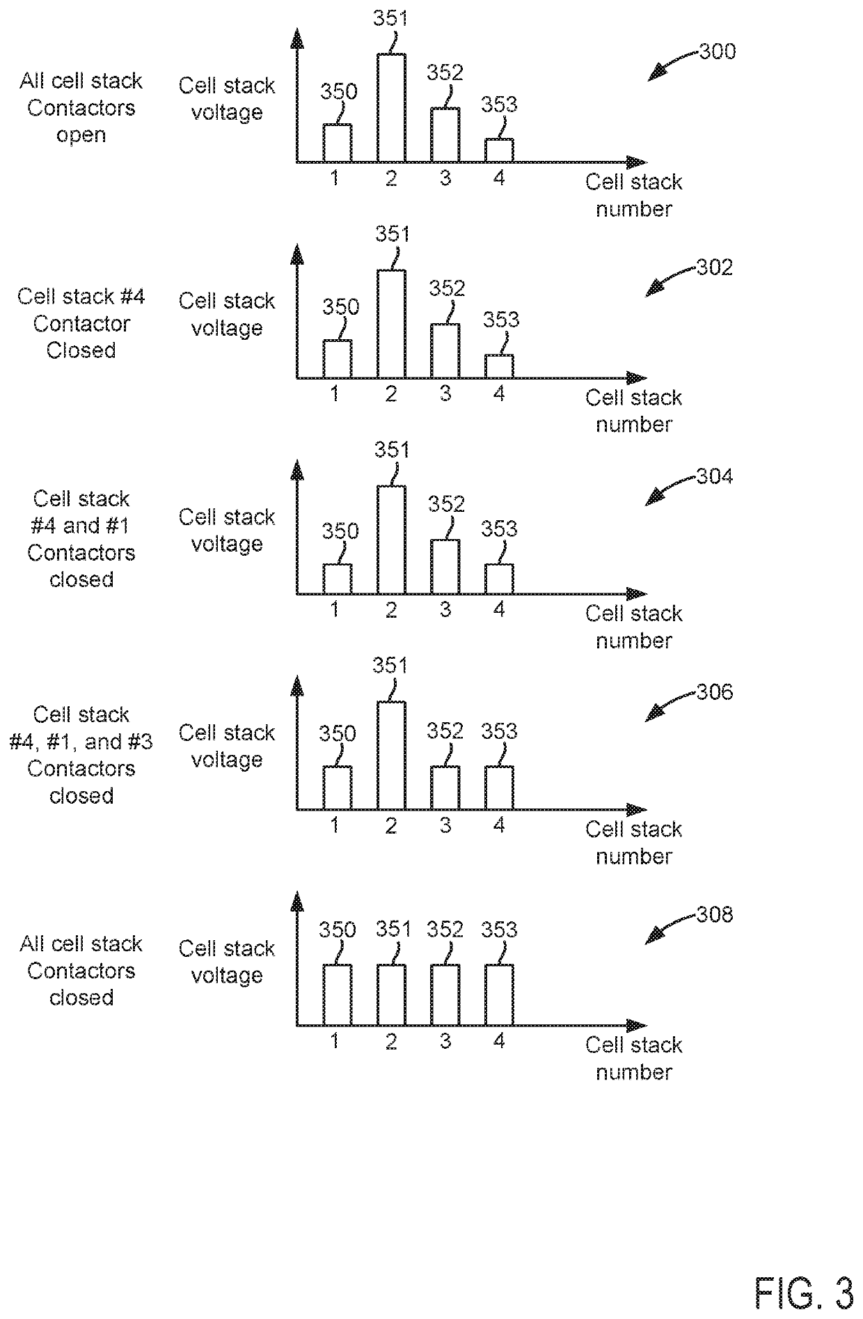
[0014]The present description is related to operating an electric energy storage system (e.g., a direct current (DC) power source) as shown in FIG. 1. The electric energy storage system may store electrical energy that is generated via photovoltaic cells, hydroelectric power, wind power, or via chemical energy. The electric energy storage system may output DC power that may be distributed as alternating current AC after a conversion process. The electric energy storage system may include an iron flow device as shown in FIGS. 1 and 2. The electric energy storage system may combine a plurality of electric energy storage cell stacks in parallel as shown in FIG. 2. The electric energy storage system may operate as shown in FIGS. 3 and 4 according to the method of FIG. 5. A method for operating the electric energy storage system is shown in FIG. 5.

[0015]Referring to FIG. 1, an example of an all iron redox flow battery (IFB) cell is shown. The IFB cell 175 is an electric energy storage ce...


PUM

PropertyMeasurementUnit
voltagesaaaaaaaaaa
output voltageaaaaaaaaaa

Abstract

Systems and methods for operating an electric energy storage system are described. The systems and methods include ways of coupling electric energy storage cell stacks to an electric conductor or bus. The coupling is performed to reduce current flow through contactors and to increase a life span of the contactors.

Description

FIELD[0001]The present description relates to a system and method for operating an electric energy storage system. The methods and systems may be particularly useful for electrical power systems that include a plurality of electric energy storage cell stacks.BACKGROUND AND SUMMARY[0002]An electrical energy storage system may include electrical energy storage cells (e.g., battery cells) that are arranged in series and in parallel. Electrical energy storage cells that are arranged in series increase the voltage potential of the electric energy storage system. Electric energy storage cells that are arranged in parallel increase the power output capacity of the electric energy storage system. The electric energy storage cells of one electric energy storage cell stack may be charged to a level (e.g., voltage) such that the voltage of the one electric energy storage cell stack that includes the electric energy storage cells is lower or higher than levels of other electric energy storage c...

Claims


Application Information

Patent Timeline
Patent Type & Authority Applications(United States)
IPC IPC(8): H02J7/00H01M8/18
CPCH02J7/0042H02J7/0013H01M8/188Y02E60/50H02J7/0032H02J1/109
Inventor VANDERZANDEN, AARONERNST, STEVE
Owner ESS TECHNOLOGY
Why Eureka
Try Eureka