
Object monitoring system including distance measuring device

Active Publication Date: 2020-04-30
FANUC LTD
View PDF0 Cites 2 Cited by
  • Summary
  • Abstract
  • Description
  • Claims
  • Application Information

AI Technical Summary

Benefits of technology

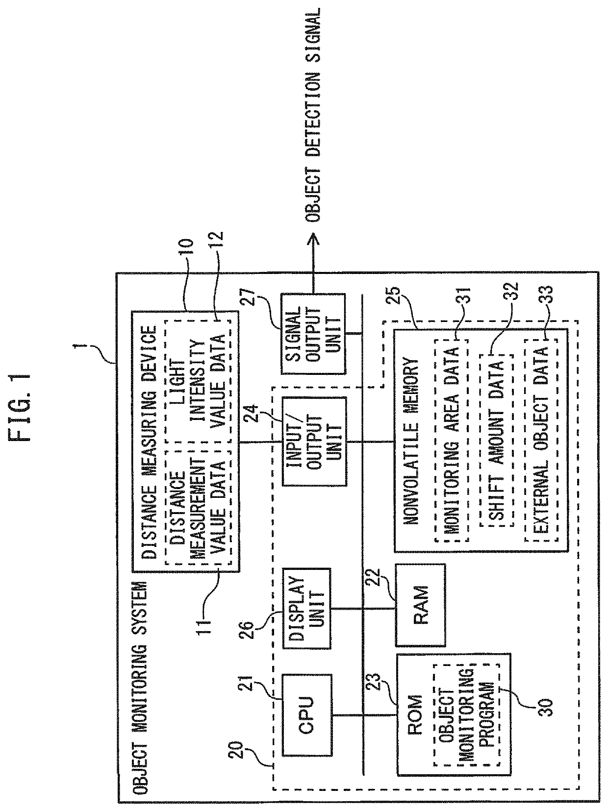
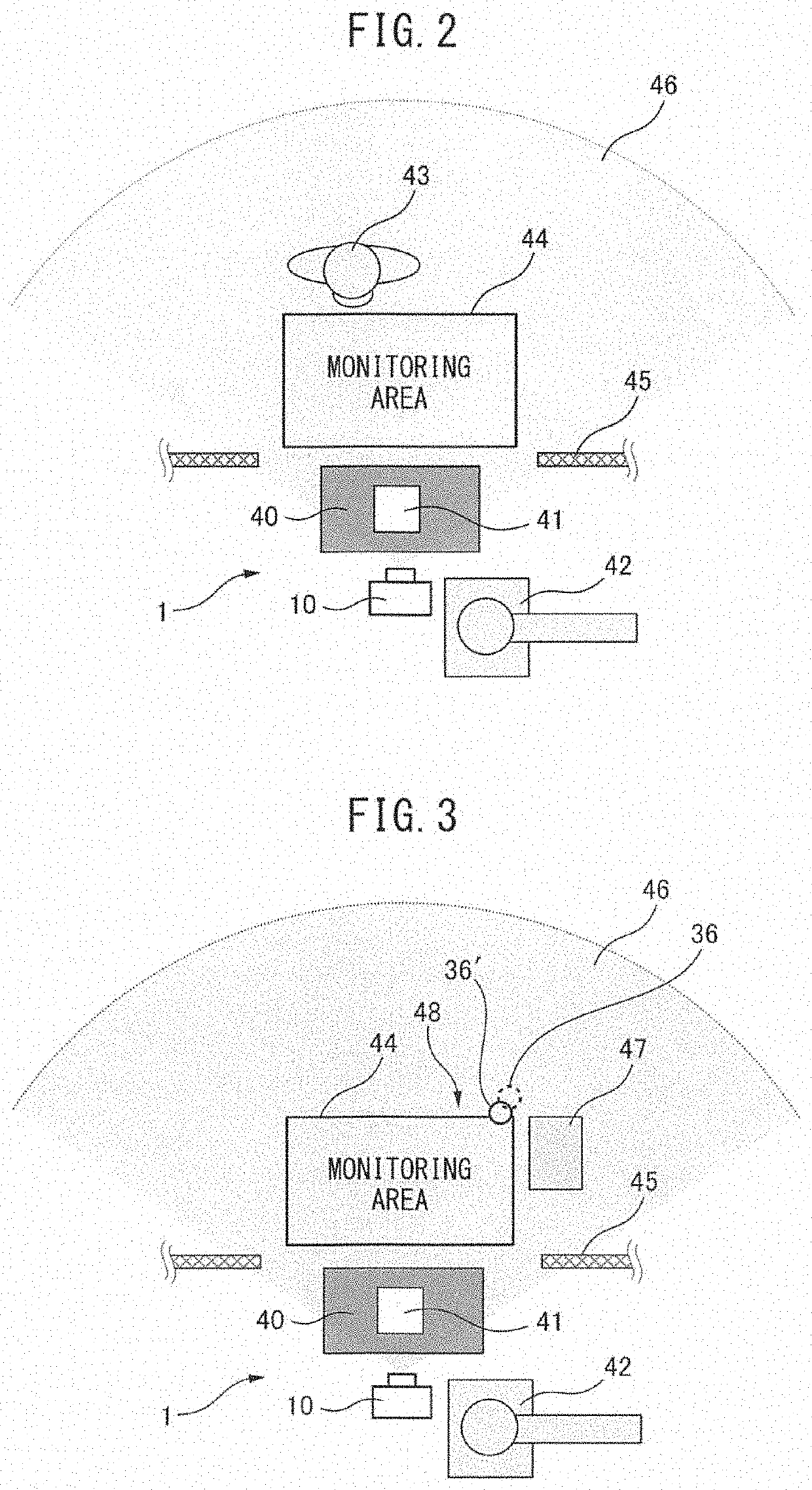
The patent text describes an object monitoring system that uses a distance measuring device to determine if an object is present in a set monitoring area. However, if there is an external object that causes the multipath phenomenon (where light is reflected multiple times) in the vicinity of the monitoring area, the distance measurement value from the camera can be erroneously large, resulting in the false determination that the object is absent. To address this issue, the system calculates the arrangement of the external object and estimates the shift in the distance measurement value caused by the external object. Based on this information, the system corrects the determination to ensure more accurate object monitoring.

Problems solved by technology

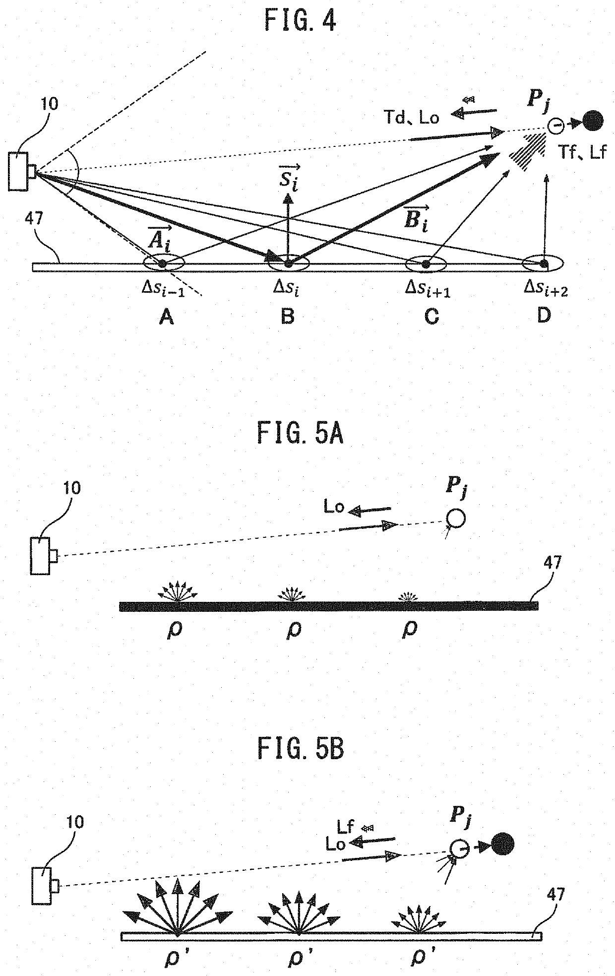
In an object monitoring system in which it is determined, using a TOF camera, whether or not a monitored object is present in a set monitoring area in a target space based on the distance measurement value, when there is an external object which causes the multipath phenomenon in the vicinity of the monitoring area, the distance measurement value output from the TOF camera can be erroneously large.
In this case, it may be erroneously determined that the monitored object is absent even when the monitored object is present in the monitoring area, particularly in distant positions in the monitoring area.

Method used


Image

  • Object monitoring system including distance measuring device
  • Object monitoring system including distance measuring device
  • Object monitoring system including distance measuring device

Examples


example 1 (

CORRECTION OF MONITORING AREA)

[0067]FIG. 12 is a contour map representing the shift amount of the distance measurement value caused by the external object 47. In order to facilitate understanding, in FIG. 12, the contours of the shift amount of the distance measurement value are shown for the monitoring area 44 and the areas in the vicinity thereof, though it should be noted that the shift amount of the distance measurement value in the present example is estimated using only the far side edge 55 of the monitoring area 44. Note that for a monitoring area 44 having a rectangular parallelepiped shape, the far side edge 55 of the monitoring area 44 is defined as the rear, right, left, top, and bottom surfaces of the monitoring area 44. By estimating the shift amount of the distance measurement value using only the far side edge 55 of the monitoring area 44, the calculation cost on the computing device can be controlled.

[0068]FIG. 13 is a plan view showing the correction of the monitori...

example 2 (

CORRECTION OF DISTANCE MEASUREMENT VALUE OF MONITORED OBJECT)

[0071]FIG. 16 is a contour map showing the correction amount of the distance measurement value caused by the external object 47, and FIG. 17 is a plan view showing a distance measurement point group 58 which is influenced by the multipath of a monitored object 36′ which has slightly entered the monitoring area. The contour lines of the correction amounts shown in FIGS. 16 and 17 represent the distribution of the correction amount (shift amount) of the distance measurement value based on the distance measurement value measured by the distance measuring device 10, i.e., the distance measuring point, (position) represented by the distance measurement value, and it should be noted that the distributions and signs thereof differ from those of the contour lines of the shift amounts shown in FIGS. 12 and 13. By estimating the correction amount (shift amount) of the distance measurement value measured by the distance measuring dev...


PUM


Abstract

An object monitoring system includes means for calculating an arrangement of an external object in a target space based on a distance measurement value of the external object, and estimating a shift amount of the distance measurement value caused by the external object in accordance with the calculated arrangement, and means for correcting, based on the estimated shift amount, determination of whether or not a monitored object is present in a monitoring area set in the target space.

Description

BACKGROUND OF THE INVENTION1. Field of the Invention[0001]The present invention relates to an object monitoring system including a distance measuring device, and in particular, relates to an object monitoring system which takes the influence of multipath into consideration.2. Description of Related Art[0002]TOF (time of flight) cameras which output a distance based on the tine of flight of light as distance measuring devices for measuring the distance to an object are known. Many TOF cameras use a phase difference method in which a target space is irradiated with reference light which is intensity-modulated over predefined cycles, and the distance measurement value of the target space is output based on a phase difference between the irradiated measurement light and the light reflected from the target space.[0003]Since such TOF cameras measure distance by indirect measurement of the path lengths of reference light based on the phase difference, the phenomenon (so-called “multipath”)...

Claims


Application Information

Patent Timeline
IPC IPC(8): G01S17/89G01S17/36
CPCG01S17/89G01S17/36G01S7/487G01S17/48G01S17/894G01S17/04G01S7/493
Inventor NAKAMURA, MINORUWATANABE, ATSUSHITAKAHASHI, YUUKI
Owner FANUC LTD
Features
  • Generate Ideas
  • Intellectual Property
  • Life Sciences
  • Materials
  • Tech Scout
  • Unparalleled Data Quality
  • Higher Quality Content
  • 60% Fewer Hallucinations
Learn More