
Device for recycling and recycling waste tires

a technology for recycling tires and tires, applied in the field of tires recycling equipment, can solve the problems of large raw material costs, waste of rubber materials, and inability to directly process steel wire, so as to save time and labor costs, save a lot of material costs, and quickly and accurately pull out.

Inactive Publication Date: 2020-05-07
WANG HUIMIAO
View PDF0 Cites 8 Cited by
  • Summary
  • Abstract
  • Description
  • Claims
  • Application Information

AI Technical Summary

Benefits of technology

The patent describes a device for recycling and recycling waste tires. The device includes a machine body with a sliding groove and a steel wire removing device. The sliding groove has a slider that can slide left and right. The steel wire removing device has a slider that can slide left and right. The device also includes a crushing cavity, a sliding chamber, and a crushing device with crushing rollers. The device can remove the steel wire from the tire and process the rubber material. The device also includes a conveying cavity and a conveying shaft for conveying the processed material. The technical effects of the device include improved recycling of waste tires and efficient processing of rubber material.

Problems solved by technology

There are still a large number of recyclable materials in discarded tires, which can save businesses A large amount of raw material costs, and thus the expansion of economic benefits, most of the current tire recycling equipment can only remove the steel wire in the tire, and the steel wire is still stuck with a lot of broken rubber, making it impossible to directly process the steel wire and Waste some rubber material.

Method used


Image

  • Device for recycling and recycling waste tires
  • Device for recycling and recycling waste tires
  • Device for recycling and recycling waste tires

Examples


Embodiment Construction

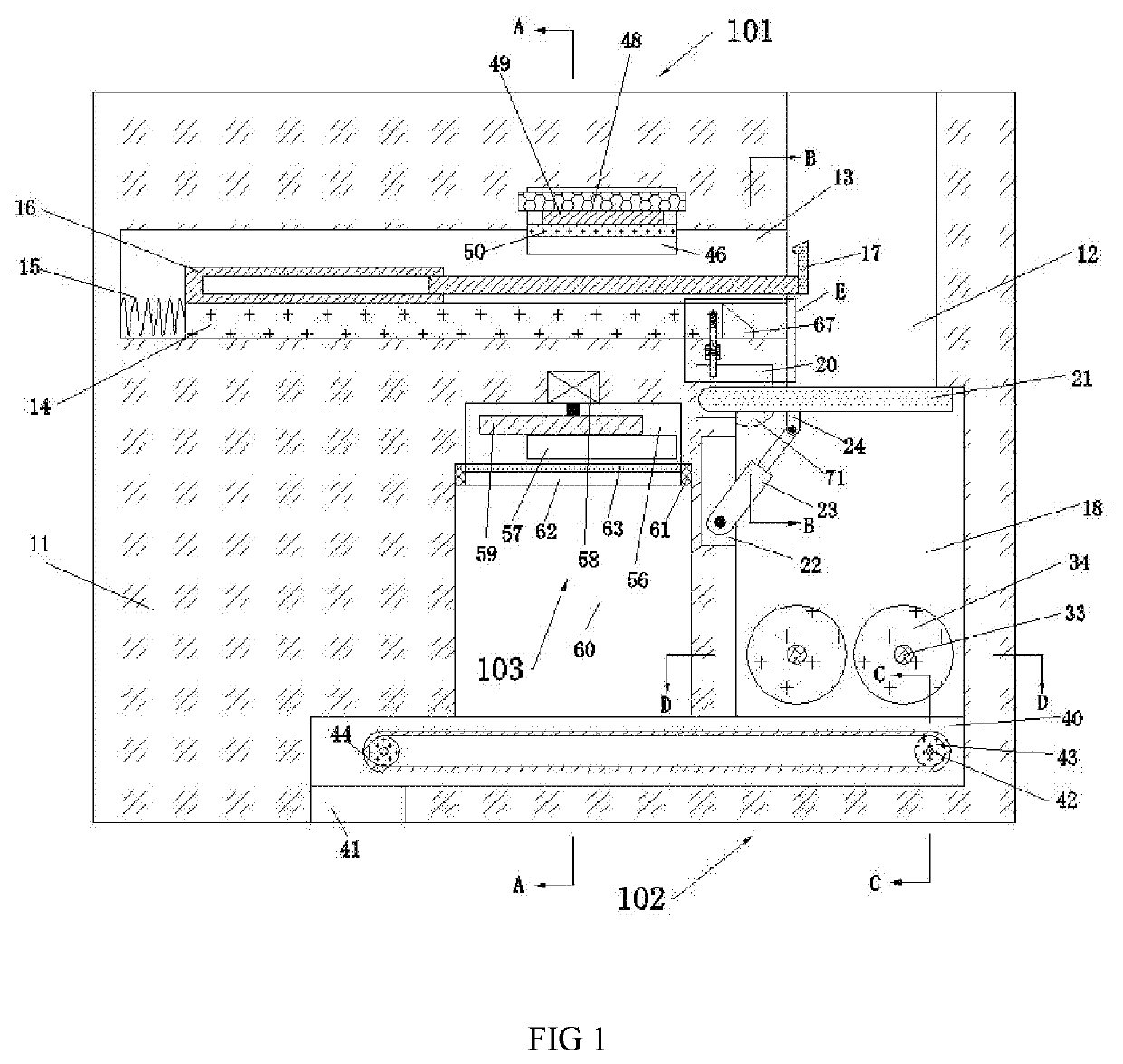
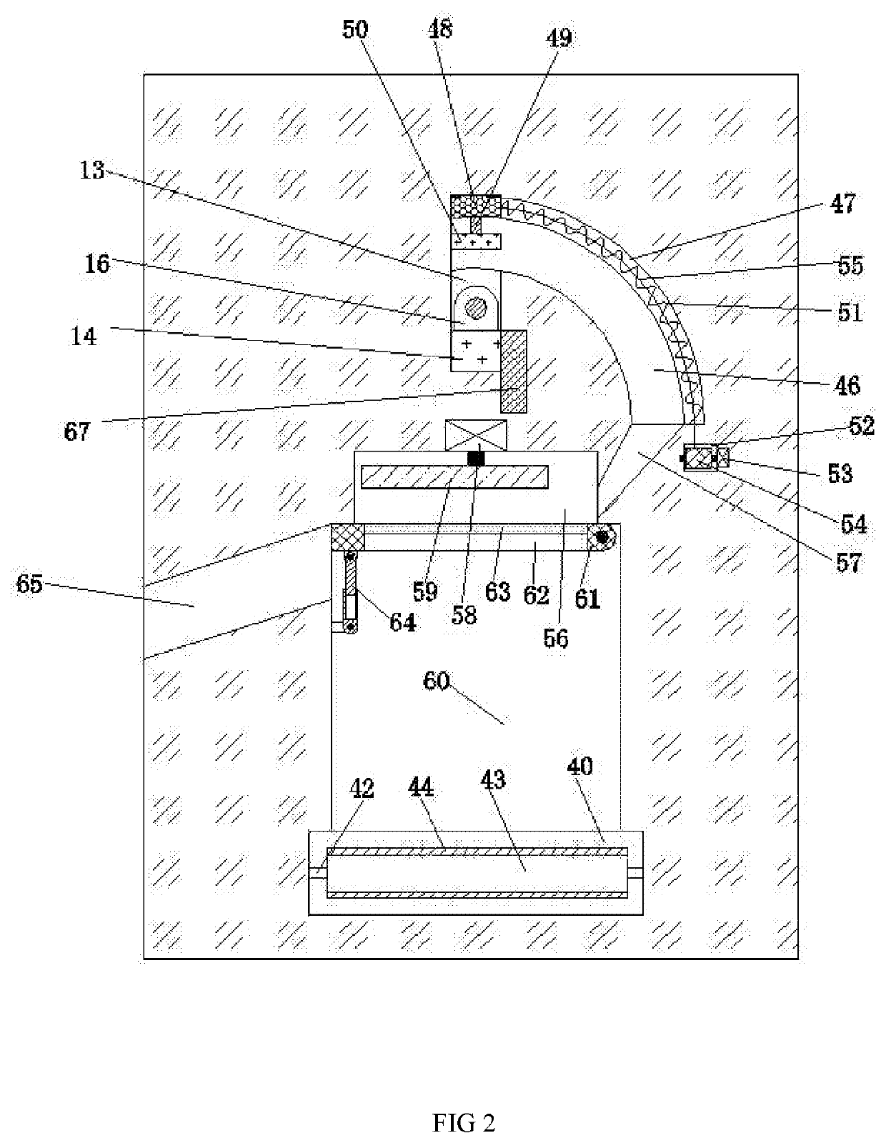
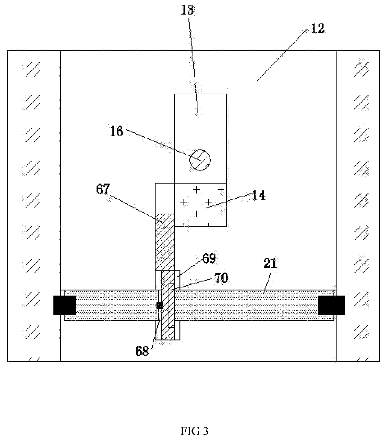
[0023]The present invention will be described in detail below with reference to FIGS. 1-6. For convenience of description, the orientation described below is defined as follows: the up-down, left-right, front-back direction described below is consistent with the up-down, left-right, front-back direction of the projection relationship of FIG. 1 itself.

[0024]The invention relates to a device for recycling waste tires, which is mainly used for recycling tires containing steel wire layers. The invention will be further described below with reference to the accompanying drawings of the invention:

[0025]The equipment for recycling waste tires according to the present invention comprises a machine body 11, an upper opening 12 is provided on the right side of the upper end surface of the machine body 11, and a chute 13 is provided on the left wall of the inlet 12 in communication. A wire removing device 101 is provided in the chute 13. The wire removing device 101 includes a slider 14 slidab...


PUM

PropertyMeasurementUnit
poweraaaaaaaaaa
structureaaaaaaaaaa
timeaaaaaaaaaa

Abstract

The invention discloses a device for recycling waste tires, which includes a machine body. The upper end of the machine body is provided with an inlet with an upward opening on the right side of the body. The left wall of the inlet is connected with a chute. The chute is provided with A steel wire removal device, a crushing cavity is connected to the lower wall of the inlet, and a crushing device is fixed in the crushing cavity. A twisting cavity is provided in the left wall of the crushing cavity and below the chute. A fourth motor is fixed in the wall, and an eccentric wheel is dynamically connected to the lower end of the fourth motor. The invention can quickly and accurately pull out the steel wire layer in the tire and twist the broken rubber stuck on the steel wire, so that the steel wire and the tire are cleaned. Recyclable materials such as rubber are separated. At the same time, the tires that have been torn out of the steel wire are broken into small pieces of rubber, which is convenient for the next processing, which not only saves the company a lot of material costs, but also saves a lot of time costs and labor.

Description

CROSS-REFERENCES TO RELATED APPLICATIONS[0001]The present application claims priority from Chinese application No. 2019108869126 filed on Sep. 19, 2019 which is hereby incorporated by reference in its entirety.TECHNICAL FIELD[0002]The invention relates to the technical field of tire recycling equipment, and in particular to a device for recycling and recycling waste tires.BACKGROUND OF THE INVENTION[0003]With the booming development of the automobile industry, people's lives are inseparable from cars. The use of cars is accompanied by the constant replacement of tires. There are still a large number of recyclable materials in discarded tires, which can save businesses A large amount of raw material costs, and thus the expansion of economic benefits, most of the current tire recycling equipment can only remove the steel wire in the tire, and the steel wire is still stuck with a lot of broken rubber, making it impossible to directly process the steel wire and Waste some rubber materia...

Claims


Application Information

Patent Timeline
Patent Type & Authority Applications(United States)
IPC IPC(8): B29B17/02B29B17/00
CPCB29L2030/00B29B2017/022B29B17/02B29B17/0047B29B2017/0224G09F15/0006B29B17/0412B29B2017/0268B29B2017/0472Y02W30/52Y02W30/62
Inventor WANG, HUIMIAO
Owner WANG HUIMIAO
Learn More